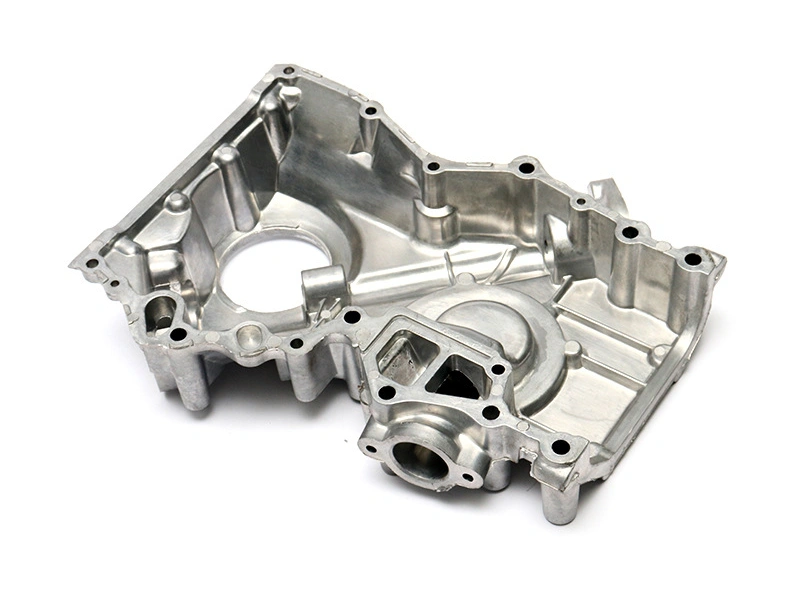
Auto Diecasting for OEM Parts: Design Release, Porosity Risk and Production Validation
Auto diecasting is a production route for automotive metal parts when the component needs repeatable geometry, integrated ribs or bosses, controlled weight, and a defined path from drawing release to inspected finished parts. The process is not selected from the word “automotive” alone. A buyer must match the alloy, die-casting method, part envelope, wall transitions, pressure or structural function, machining datums, leak or fatigue risk, and planned production volume. The most useful automotive die-casting RFQ is therefore a controlled engineering package, not just a vehicle program name and an annual quantity.
For an OEM or Tier supplier, the production decision begins before the die is designed. A drawing must distinguish as-cast surfaces from machined interfaces, cosmetic areas from hidden areas, and nominal geometry from inspection datums. The supplier should review flow, venting, overflow, ejection, trimming, and tool maintenance alongside the part function. When the casting will be machined, metal casting and post-machining should be quoted as a connected route.
Define the Automotive Part Function First
An engine cover, transmission housing, motor bracket, sensor enclosure, structural node, valve body, and cosmetic trim piece can all be described as auto diecasting, but they have different acceptance risks. A housing may need leak control and stable sealing faces. A bracket may need load-path continuity and resistance to distortion during fastening. A sensor enclosure may need clean machined interfaces, shielding features, and a finish that does not obstruct connectors. A visible trim part may prioritize surface appearance and plating or paint compatibility.
Start the RFQ with the load, pressure, temperature, vibration, chemical exposure, and assembly conditions that can be stated. If the value is unknown, say what test or design analysis will establish it. Do not transfer a requirement from a different vehicle component simply because the geometry looks similar. The supplier needs to know whether a pore near a nonfunctional rib is acceptable, whether a pore under a seal is prohibited, and whether a machined bore carries a bearing, shaft, sensor, or fastener.
The function also controls which features should be cast and which should be machined. A cast-in boss can reduce operations, but it may introduce local solidification and porosity behavior that a machined billet would not have. A near-net flange can reduce machining time, but the sealing face still needs a stable datum and enough stock. The decision should be made by function and evidence, not by a general promise of “complex automotive shapes.”
Part function | Design question | Validation evidence |
|---|---|---|
Sealed housing | Where are the pressure boundaries, gasket lands, and leak paths? | Leak test plan, sealing-face inspection, porosity review, and assembly trial |
Load-bearing bracket | Which ribs, bosses, and fillets carry the load into the mounting points? | Structural analysis, material confirmation, dimensional inspection, and functional test |
Machined bore part | Which datums control bore alignment and final fit? | Fixture plan, bore measurement, runout or position check, and mating trial |
Visible trim or cover | Which surfaces require a finish master and which defects are visible? | Representative sample, visual limit, coating or paint inspection, and packaging review |
Alloy and Process Selection
Aluminum die casting is often considered for automotive housings and brackets because it can combine lower density than steel with castable geometry and a machining route. The alloy still has to match the part. A casting alloy selected for fluidity and production behavior may not provide the same corrosion, thermal, pressure-tightness, or machining response as another alloy. The drawing should name the required material designation or define how an equivalent will be approved.
Process selection depends on more than machine size. High-pressure die casting can support detailed, thin-walled production parts, but the filling pattern, air entrapment, die temperature, venting, and overflow design affect internal soundness. Gravity or low-pressure routes may be considered for different section sizes, pressure behavior, or lower-volume conditions. The right route must be checked against the part's walls, core needs, feature density, quantity, and downstream machining.
Aluminum die casting should be reviewed with the intended surface treatment and assembly sequence. An alloy that is suitable for a painted housing may not deliver the same cosmetic result under a demanding anodizing requirement. A part that is pressure-sensitive may need an alloy and process review before tooling. The RFQ should also identify whether recycled content, heat treatment, impregnation, or another special condition is required, because each can change cost and validation.
Design the Die Around Flow and Venting
Auto diecasting quality is strongly influenced by how molten metal fills the cavity and how air and gases leave it. A long flow path, abrupt wall change, isolated boss, thin rib, or blind pocket can create a local filling or solidification concern. The supplier's die design should show how gates, runners, vents, overflows, slides, cores, and ejectors relate to the part. A buyer does not need to approve every tool detail alone, but should understand which features control the risk areas identified during design review.
Wall thickness should be designed for the chosen process rather than made uniform by habit. Sudden heavy sections can cool later and create shrinkage-related discontinuities. A rib that is too thick relative to the wall may act as a heat sink or create a visible sink or distortion risk. A core can create a useful internal passage, but it adds tool complexity, alignment demands, and a surface that may require inspection or machining.
Venting and overflow design deserve attention when a part contains sealed volumes or machined pressure boundaries. A vent mark may be acceptable on a hidden edge but not on a sealing face. An overflow may be trimmed away, but the trim line still needs a boundary. Discuss these details while the tool is being reviewed. Moving a gate or vent after steel is cut is more expensive than resolving the parting and flow strategy during DFM.
Porosity Is a Risk Map, Not a Single Number
Porosity in a die cast automotive part is not automatically a reject or an acceptance. Its position, size, connection to the surface, distance from a pressure boundary, effect on a machined feature, and response to the intended service load all matter. A pore in a hidden low-stress area may be treated differently from a connected pore under a gasket land or inside a bearing bore. The buyer and supplier need to agree which regions are sensitive and which evidence will be used.
Machining can open subsurface porosity. A casting that looks sound before machining may reveal cavities when a face is cut. That is why the machining allowance, datum strategy, and inspection plan should be reviewed together. Engineering review can help identify pressure boundaries and load paths before tooling, while production inspection can check the finished features that the casting alone cannot prove.
Do not use an unsupported universal porosity percentage or a vague “pore-free” promise. Define the method, location, sampling, and acceptance threshold required by the program. Depending on the part, evidence can include visual inspection, sectioning of qualification samples, radiographic inspection, leak testing, dimensional checks after machining, or functional tests. The right evidence is chosen from the failure mode and customer requirement.
Risk location | Why it matters | Possible verification path |
|---|---|---|
Sealing face | A connected pore or surface break can create a leak path | Finished-face inspection and leak test under agreed conditions |
Bearing or shaft bore | Machining may expose porosity or reduce support around the fit | Bore inspection, section review, and functional assembly |
Fastener boss | Local defects can affect clamp load transfer or thread integrity | Thread or insert check, dimensional inspection, and fastening trial |
Hidden low-load rib | May have lower consequence, but the boundary must be explicit | Process monitoring and sampled inspection against the drawing zone |
Machining and Datum Control
The as-cast part is not automatically a reliable machining reference. A casting can have draft, parting variation, trim variation, and local distortion. If a bore, sealing land, and mounting face are all machined from an unstable reference, the finished relationship can move even when each feature is individually within a simple size tolerance. Define which surfaces locate the casting in the fixture, which surfaces establish the functional coordinate system, and which features must be inspected in relation to one another.
Machining allowance should account for casting variation without hiding a process problem. Too little stock can leave a defect or an incomplete face. Too much stock can expose more porosity, increase cycle time, and remove a useful cast surface. The supplier should show how the allowance relates to the tool design, parting line, expected variation, and final tolerance. A drawing that specifies tight finished dimensions but leaves the as-cast condition undefined transfers risk to the first production trial.
Automotive assemblies often expose errors through stack-up rather than through one part dimension. A housing bore, cover face, locating boss, and connector opening may each pass a local check but fail when assembled. Use a fixture or mating-part trial for the features that control the assembly. Inspection reports should preserve the same datums used by the design team, otherwise the report can appear complete while missing the relationship that matters.
Validation From Sample to Repeat Production
Automotive validation should move from design evidence to production evidence in stages. Early samples can answer whether the geometry fills, whether the machining approach works, and whether the part assembles. Tool-trial samples can reveal gate marks, flash, vent traces, ejection marks, distortion, and porosity behavior. A production-intent sample should be made with the intended die, alloy, trimming, machining, finish, inspection, and packaging route. A sample made by a different process can validate some design questions but cannot automatically approve the production route.
Keep a controlled record of the approved drawing revision, alloy designation, tool revision, process changes, inspection equipment, fixture, and sample condition. When a supplier proposes a change, decide whether it affects form, fit, function, appearance, durability, or traceability. The change may be minor from the toolmaker's view and still significant to the vehicle assembly. A repeat order should be released against the approved records rather than against a remembered sample.
Functional tests must be tied to the part's role. A leak test does not prove structural durability. A dimensional report does not prove that a connector mates. A visual approval does not prove coating adhesion. Use a test matrix that separates qualification evidence from routine production checks, and define which records are supplied with each lot. This makes the manufacturing route auditable without pretending that one inspection method proves every requirement.
What an OEM Auto Diecasting RFQ Should Contain
Send the 3D model, controlled drawing, material designation, part mass or envelope, annual and lot quantities, expected launch stage, critical characteristics, pressure or leak boundaries, load cases, environmental conditions, machining requirements, surface finish, coating or paint requirement, inspection standard, packaging, and change-notification expectations. Mark customer-supplied components, inserts, seals, or fasteners that affect the quote. If the design is not frozen, identify the open items and ask the supplier to price the design review separately from production tooling.
Ask for a DFM response that names the proposed parting line, gate and overflow approach, slides or cores, draft concerns, machining datums, high-risk sections, and inspection plan. Ask how defects will be contained if the first trial shows a leak path, open porosity, or distortion. The answer should show an engineering decision, not only a promise to “optimize the process.”
Neway's tool and die making route can be included in the scope when tooling design, machining, trial, maintenance, and repeat-order records need to be coordinated. State who owns the tool, who approves revisions, who pays for changes caused by customer design changes, and what documents are delivered at the production release. These commercial details protect the engineering schedule as much as the casting process does.
Records That Protect Repeat OEM Orders
Repeat production is easier to control when the approved part is represented by more than a purchase order. Retain the released drawing, 3D model revision, material designation, die revision, trim definition, machining program revision, fixture, inspection plan, finish specification, and packaging instruction. The exact records depend on the customer program, but the principle is consistent: a repeat order should be traceable to the same manufacturing assumptions that were validated.
Material records should distinguish the specified alloy from a general label such as “automotive aluminum.” If a substitute is proposed, compare its casting behavior, machinability, corrosion response, thermal behavior, and effect on the finish. The supplier should state which tests or measurements will demonstrate equivalence. A material certificate can identify a lot, but it does not by itself prove that a different alloy will fill the same die or support the same leak and machining result.
Tool maintenance records matter because die condition can influence flash, parting mismatch, cooling balance, dimensions, and surface marks. Track planned maintenance and repair decisions against the tool areas that affect critical features. If a gate, vent, insert, slide, or cavity is modified, the change should be reviewed against the inspection plan. It is much easier to investigate a recurring defect when the tool history is available.
Packaging is part of the production route for auto diecasting. Cast and machined faces can be damaged during bulk handling even when the part passed final inspection. Define separators, caps, rust or moisture protection where needed, orientation, quantity per container, and identification. Packaging should protect the features that the assembly needs and should not introduce residue that later interferes with coating, sealing, or electrical contact.
Containment When the First Trial Misses
A first tool trial can miss a dimensional target, show unexpected porosity, or produce a surface that is not suitable for the planned finish. The response should separate immediate containment from permanent correction. Sorting or holding parts may protect the assembly line, but it does not explain whether the cause is die temperature, gate balance, machining fixture, tool wear, alloy condition, or drawing interpretation.
Ask the supplier to record the affected zone, lot, process stage, defect evidence, temporary action, and decision owner. For example, a leak at a machined land should be checked against casting porosity, machining depth, surface flatness, gasket design, and test setup. A bore position issue should be checked against the casting datum, fixture support, tool movement, and measurement method. A good containment record keeps the team from applying a cosmetic fix to a structural problem.
Do not release a permanent change on the basis of one visually improved sample. The change needs a defined recheck of the affected characteristics and any linked characteristics. Moving a gate can improve a flow mark and change machining stock. Adding a support rib can improve stiffness and alter section thickness. Changing a coating can improve appearance and affect connector fit. The validation scope follows the change mechanism.
Release Gates for Auto Diecasting
Before tooling release, confirm the part function, alloy, process route, parting and flow strategy, wall transitions, cores, draft, machining allowance, datums, porosity-sensitive zones, finish requirements, and validation plan. Before production release, confirm the tool revision, production-intent samples, inspection records, functional tests, packaging, and change-control contacts. Before a repeat order, confirm that the same approved material, tool, machining route, finish, and acceptance plan remain in force.
Auto diecasting works best when it is treated as a controlled system linking design, tool, casting, machining, inspection, and assembly. A supplier quote becomes meaningful when it explains those links and identifies what still depends on the final drawing, alloy, geometry, quantity, and inspection plan. That is the standard an OEM buyer should use when comparing production routes.
Approve the Vehicle Part After the Last Operation
If the OEM receives a machined, finished, or assembled part, use that state for the final interface and functional approval. A raw die-cast sample remains useful for process learning but cannot prove the delivered condition.
FAQ