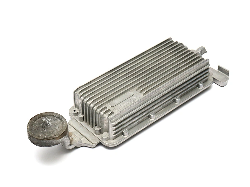
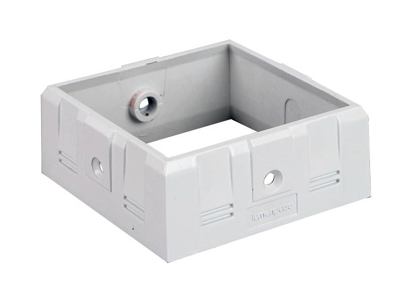
Die Cast Aluminum Enclosure Wall Thickness: Why 3 mm Is a Starting Point
A 3 mm wall is a useful starting point for many die cast aluminum enclosures, but it is not a universal design rule or a guaranteed production result. The suitable wall depends on the casting process, alloy, enclosure size, flow length, rib layout, draft, sealing requirement, local bosses, machining allowance, cosmetic surface, and production quantity. A thin wall may fill in one location and fail in another if metal must travel around a corner, pass a narrow gate, or feed a heavy boss. Buyers should therefore specify the wall as part of a complete enclosure design rather than ask whether a supplier can “cast 3 mm” in isolation.
For a custom housing, start with the functional boundary: what must the wall contain, shield, seal, support, or protect? A cover that carries a gasket, a sensor enclosure with an EMI requirement, a motor housing with a bearing seat, and a simple protective shell need different design reviews. Aluminum die casting can integrate ribs, bosses, mounting features, and heat-spreading surfaces, but the final wall and feature transitions should be confirmed against the actual alloy and tool layout.
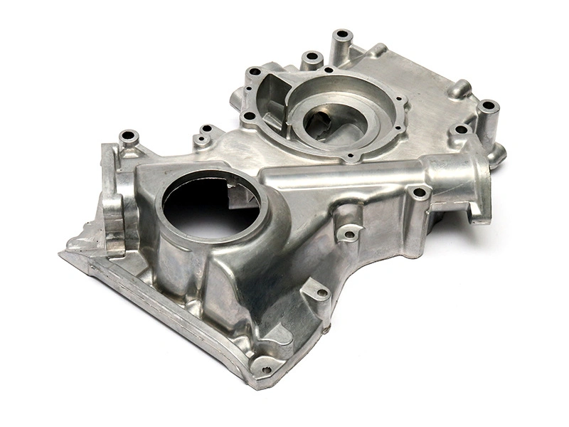
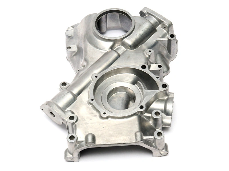
What the 3 mm Question Is Really Asking
When a buyer asks for a typical 3 mm wall thickness, the underlying question is usually whether the enclosure can be made without excessive tooling risk, distortion, porosity, or machining cost. The answer requires more detail than the nominal number. Is 3 mm the minimum local wall, a broad nominal wall, or the remaining thickness after machining? Is it on a straight exterior panel or beside a rib, corner, connector opening, or gasket land? Is the surface cosmetic, structural, thermal, or hidden?
A broad 3 mm panel may behave differently from a 3 mm web between two heavy bosses. A long side wall may need a different gate and vent arrangement from a small cover. A wall near a heat sink or bearing boss can experience a strong section change. If the part must be pressure-tight, a wall that looks adequate in a CAD section may still be affected by internal discontinuities or a machined pocket. These questions belong in the DFM review before the die is released.
Use a wall-thickness map rather than one note. Mark nominal walls, local minimums, heavy sections, ribs, bosses, openings, sealing faces, and surfaces that will be machined. Then ask the supplier to identify which zones are process-sensitive. This produces a useful engineering conversation and prevents “3 mm” from being read as an unconditional guarantee.
Enclosure zone | Why 3 mm may behave differently | Buyer action |
|---|---|---|
Broad side wall | Flow length, venting, and cosmetic distortion govern the result | Show flow direction, cosmetic boundary, and flatness requirement |
Wall beside a boss | Local heavy section can change cooling and shrinkage behavior | Review boss blend, rib thickness, and machining allowance |
Gasket or sealing wall | Surface integrity and final datum matter more than nominal cast size | Define machining, leak test, flatness, and pore-sensitive zone |
Connector opening | Thin edges, slides, flash, and assembly clearance interact | Review draft, trim line, masking, and connector trial |
Alloy and Process Change the Wall Answer
Aluminum alloys are not interchangeable in a wall-thickness discussion. Fluidity, solidification behavior, silicon and copper content, pressure-tightness expectations, machinability, corrosion exposure, and surface-finish requirements influence the practical design window. A material selected for a cost-sensitive housing may need a different wall transition from a material selected for a pressure-sensitive or corrosion-exposed part.
High-pressure die casting can produce detailed geometry and thin sections, but the process must be designed around filling, air evacuation, die temperature, gate velocity, and ejection. Gravity or low-pressure casting may suit a different volume, section size, or internal quality requirement. A supplier should review the part envelope and quantity before declaring the process route. “Die cast” is not enough detail to establish a minimum wall.
Alloy selection also affects downstream finishing. A cast aluminum enclosure intended for powder coating may tolerate a different visible surface condition from a part expected to receive a demanding anodizing finish. A housing that will be machined for a seal may need an alloy and process with a suitable internal quality. Link the wall review to the end-use requirement rather than treating material as a separate purchasing field.
Ribs, Bosses, and Corners Need Transition Control
Ribs help stiffen an enclosure without adding a solid block of metal, but a rib that is too thick can behave like a heavy section. The rib-to-wall junction should be blended so the metal can fill and cool without a sharp volume change. Rib height, draft, spacing, and orientation affect both the die and the finished part. If a rib becomes a machining or assembly reference, add that requirement to the drawing instead of relying on the nominal cast profile.
Bosses are common for screws, inserts, bearings, connectors, and mounting points. A boss needs enough material to support the feature, yet a thick isolated boss can increase shrinkage, porosity, and cycle variation. Hollow or cored bosses may reduce mass and section thickness, but add core, slide, or tool alignment decisions. The final hole may be cast, drilled, reamed, or interpolated by CNC depending on the fit and the process capability that the project can support.
Outside corners, inside corners, and openings also influence flow and stress. A small radius can create a sharp visual line and a local filling concern. A generous radius may improve casting behavior but change the external envelope or mating fit. Mark the functional radii and ask for alternatives when the cosmetic target conflicts with manufacturability. Good DFM is a negotiated geometry decision, not a generic request to “add more radius.”
Draft, Parting, and Ejection
A 3 mm wall does not make an enclosure easy to remove from the die. Draft, parting direction, slides, lifters, ejector locations, and the intended cosmetic faces must be reviewed together. An opening that appears straight in CAD may need a slide or a change in parting to avoid an undercut. A small draft can preserve a tight exterior envelope, but may increase ejection marks, scuffing, or tool wear depending on the surface and depth.
Parting lines should be kept away from gasket lands, connector interfaces, and highly visible surfaces where possible. That is a design preference with a functional reason: a parting mismatch or flash line can interfere with sealing or assembly. When the line must cross a visible face, define the acceptable boundary and finishing operation. If the line crosses a machined pad, the machining allowance and fixture datum need to account for the cast variation.
Ejectors leave marks, and the marks are not equally acceptable everywhere. A hidden internal wall may tolerate an ejector print; a cosmetic face or a sealing surface may not. The DFM response should identify ejector and overflow locations and show how the part will be trimmed. This is especially important for a compact enclosure where a large share of the surface is visible after assembly.
Machining and Sealing After Casting
Many enclosures are finished parts rather than raw castings. Gasket lands, bearing seats, connector bores, mounting holes, datum pads, and cover interfaces may require CNC machining. CNC post-machining should be planned into the wall and boss design. The drawing should show pre-machining stock, final dimensions, datums, flatness, position, surface texture, and any pore-sensitive area where machining could open a leak path.
Machining a thin wall can release stress or reduce stiffness during fixturing. A fixture that clamps the part too hard can distort a cover; a fixture that references an unstable as-cast face can transfer casting variation into the finished interface. Use functional datums and support surfaces that represent how the enclosure is assembled. If the enclosure is tested for leakage after machining, specify the test condition and the surfaces included in the boundary.
Do not solve every enclosure problem by adding machining stock. Extra stock increases cycle time, tool wear, chip volume, and the chance of exposing internal discontinuities. It can also make a nominally 3 mm wall much thinner after a deep pocket is cut. The correct allowance is determined from casting variation, machine route, and final function.
Thermal, EMI, and Assembly Features
Enclosures often combine several requirements. A motor or power-electronics housing may need to conduct heat through a wall or a machined pad. A sensor or control enclosure may need an electrically continuous shield or a grounding surface. A consumer or industrial housing may need a gasket, connector, screw bosses, and a cosmetic coating. Wall thickness should be reviewed against those interfaces instead of optimized only for casting weight.
Thermal paths require contact surfaces that are flat and stable after machining. If a heat sink or thermal interface material contacts a cast wall, the contact pad may need a controlled surface texture and flatness. Ribs can support stiffness but may not replace a designed thermal path. Coatings may add thickness or thermal resistance, so identify whether the thermal face is masked or machined after finishing.
EMI shielding depends on material continuity, contact pressure, grounding, and the finish at the mating interface. A painted or powder-coated surface may not conduct unless a grounding zone is masked or cleared. Anodizing or other surface treatment can change electrical behavior. The drawing should identify the grounding points and the assembly test that proves continuity; “aluminum enclosure” by itself does not establish shielding performance.
Requirement | Feature to control | Release evidence |
|---|---|---|
Thermal transfer | Machined pad, flatness, contact area, and coating exclusion | Surface measurement and assembled thermal-interface check |
EMI or grounding | Conductive zones, fastener contact, masking, and continuity path | Continuity test and mating assembly inspection |
Environmental sealing | Gasket land, screw bosses, wall transitions, and leak boundary | Finished-part leak test and sealing-face report |
Service assembly | Thread depth, insert support, clearance, and tool access | Fastener trial, torque condition, and dimensional report |
How to Validate a 3 mm Enclosure
Begin with a drawing review that maps the nominal wall, local minimums, ribs, bosses, openings, parting direction, draft, and machining features. Ask the supplier to flag sections where a 3 mm target conflicts with the chosen alloy, gate position, or tool design. A prototype can validate ergonomics and assembly, but a prototype made by CNC or 3D printing cannot fully prove die-casting fill, porosity, flash, ejection, or surface texture.
Tool-trial samples should be inspected before finishing hides evidence. Record wall-related distortion, parting mismatch, flash, surface marks, boss position, hole condition, and machined-face behavior. If a sealing or pressure boundary exists, test it in the finished state. If the enclosure is coated, approve a representative coating sample with the same masking and fit surfaces. A painted cover can fit differently from an uncoated cover if the coating thickness is not controlled.
Use sectioning or other internal inspection only where it answers a defined risk. A section through a noncritical wall is not proof of the entire enclosure. Likewise, a single wall-thickness measurement does not prove all locations. The inspection plan should identify the zones that affect assembly, sealing, thermal contact, electrical continuity, and structural function.
RFQ Inputs and Project Boundaries
Send the 3D model, controlled drawing, material designation, enclosure envelope, wall map, expected volume, tooling stage, machining requirements, finish, gasket or pressure boundary, EMI or thermal requirements, inspection method, packaging, and required records. Mark which surfaces are cosmetic and which are hidden. Include connector and fastener models when clearances matter. State whether the quote is for tooling only, cast blanks, machined housings, coated parts, or an assembled product.
Ask for the supplier's proposed parting line, gates, vents, slides, ejectors, draft changes, rib or boss changes, machining datums, and wall-risk locations. Ask which points require design approval before tool steel is cut. Do not accept a fixed statement that 3 mm is “guaranteed” without a drawing revision, alloy, process, location, and inspection method.
Neway can review tool and die making, aluminum casting, machining, and surface treatment as connected steps when the scope is defined. The final quote should separate tooling, casting, machining, finishing, inspection, packaging, and any special validation. That separation makes the wall-thickness decision visible in both engineering and commercial terms.
Cost and Scale Effects of Wall Design
Wall thickness affects more than metal weight. A section that is difficult to fill can require a different gate, additional venting, a slide, a core, a slower or more controlled process window, or extra inspection. A wall that is easy to cast but difficult to machine can consume more fixture time and create more chips. A wall that is acceptable as-cast but visually inconsistent after coating can increase sorting and finishing cost. These effects should be considered before a nominal weight target is optimized.
Tooling cost should be compared with the expected production route. A simple enclosure with open sides may need fewer slides than a housing with connector undercuts, internal bosses, and an enclosed cavity. A core can solve a geometry problem, but it introduces core location, draft, ejection, and surface questions. A design change that removes one undercut may reduce tool complexity and improve reliability, even if it adds a small amount of machining or changes the fastener direction.
Low-volume and high-volume projects may make different choices. For a low quantity, CNC machining, a simpler casting method, or a bridge tool can be reasonable while the enclosure is being validated. For repeat production, a die-cast route may justify tooling that integrates ribs, bosses, and near-net geometry. The break-even point cannot be stated without part size, alloy, quantity, cycle assumptions, tooling scope, machining, finish, and inspection. The buyer should ask for a route comparison using the actual part rather than a generic volume rule.
Surface Finish and Enclosure Appearance
As-cast texture, flow marks, ejector prints, parting lines, trim edges, and small pits can all become visible after paint, powder coating, or another finish. A coating does not make the base casting specification disappear. If the enclosure has a large visible panel, identify the cosmetic zone and the acceptable surface condition before tooling. A hidden interior may accept a different texture from an exterior panel or a bezel interface.
Surface treatment can also change fit. Coating buildup around connector openings, screw bosses, grounding pads, and cover joints may reduce clearance. Masking can protect those features, but it must be included in the drawing and quote. Post-process finishing should be reviewed with the enclosure's visual and functional zones rather than selected after the casting has already been approved.
Finish approval should use a production-representative housing or a sample that reproduces its difficult geometry. A flat panel can show color and gloss but not the way a coating bridges a rib, collects in a recess, or thins on an edge. Record the viewing condition, sample revision, visible zones, and no-plate areas. This prevents a later dispute where one team compares a color chip and another compares an assembled enclosure.
Bottom Line for Buyers
Use 3 mm as a design starting point, not as a universal minimum. The acceptable wall is the result of alloy, casting process, geometry, flow, draft, section transitions, machining, finish, and inspection. If the enclosure is sealed, thermally functional, electrically grounded, or structurally loaded, the relevant requirement is the finished interface and its evidence, not the nominal wall shown in one CAD section.
A strong enclosure RFQ turns the 3 mm question into a controlled decision: where is the wall, what does it do, how will the die fill it, what may be machined or coated, and how will the finished part be tested? That is the level of detail needed to compare a custom aluminum die-casting route responsibly.
Approve the Enclosure as an Assembly Component
Review the housing after machining, coating, sealing, and cover assembly. A nominal wall can pass a section review while the finished connector, gasket, or grounding interface still fails.
Where the enclosure route remains open, compare the finished requirement with Neway's metal casting options before freezing the wall map.
FAQ
How Should Buyers Choose an Aluminum Alloy for an Enclosure?
How Should Porosity and Warpage Be Controlled in Aluminum Housings?
What Production and Surface Records Should an Enclosure Supplier Provide?
What Wall Features Matter Most in an Aluminum Die Cast Enclosure?
Which Enclosure Features Usually Need CNC Machining After Casting?