Aluminum Casting Porosity: The Skin Hides It Until the Cut
A flange face machined to the 0.05 mm flatness target opens gas pores cast below the skin. On this 4–6 mm A356 elbow the skin is densest, chilled first by the metal mold, so pores sit under solid-looking metal. Machining removes the cover, and the pore remains a casting defect.
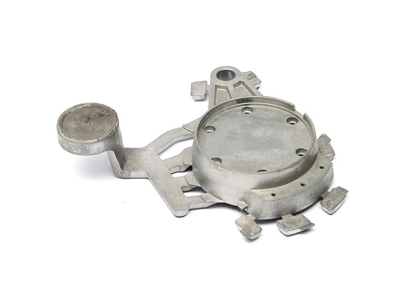
The part is a 75×60×55 mm A356 elbow (GB/T 1173 ZL101A, pending sign-off) weighing 150±20 g, cast by metal-mold gravity casting in the as-cast F temper. Porosity here means gas pores, round voids frozen in as dissolved gas comes out of solution.
What makes porosity show up after machining a flange face?
A 0.05 mm flatness callout needs a cut surface that reaches below the cast skin. The tool crosses the full Ø60±0.5 mm disc, removing metal across the sealing band. A pore frozen under the skin then breaks open as a dark pit.
The cut uncovers a pore in the 4–6 mm wall; it does not create one. The sign is on the part: a cast pore has a round, smooth wall with no torn lip or smeared metal, and the openings cluster where the skin was thinnest across the face. A part that passed a visual check can fail after turning.
Why are gas pores hidden below the surface?
A 4–6 mm wall freezes from the mold face inward, and the first metal to set forms a dense skin that seals the section. The interior stays liquid longer, so gas cannot escape and collects as round pores.
A leak at the bend found by the 0.9 MPa test, and a dark pit on the flange face, come from two different voids. Shrinkage sits at the inner bend, where the section is heaviest and feed runs short; a gas pore sits under the skin and shows at the cut. The fixes differ: tooling for shrinkage, melt treatment for gas.
How much of the cast surface must the face cut remove?
The face cut works to a 0.05 mm target across the Ø60±0.5 mm flange, with no skin inside the sealing band. Skin left in the band sits above the cut surface, so a plate and a feeler read the skin rather than the face.
The machining pass can also open a pore, and a distorted casting needs a deeper cleanup. The allowance on the drawing sets both risks: too little leaves skin in the band, too much cuts deeper and opens more pores. The Sa 2.5 blast (ISO 8501-1) runs before the face and port are cut; neither is blasted afterward, so the cut stays bare and a pore in it is visible.
How is porosity on a flange face accepted or rejected?
Of the checks here, only the 0.9 MPa, 60 s pressure test proves a leak path through the 4–6 mm wall, whatever void made it, and it runs after machining. The figure is an acceptance criterion, not a pressure rating; visual inspection with a magnifier checks the face first, then penetrant testing (PT) finds openings that reach the surface.
PT runs on the machined surfaces, so a pore that opens only on the port bore does not register on the flange face: the 0.05 mm face can pass while the pore remains.
The table sets a binary line: no opening anywhere in the sealing band, no leak at 0.9 MPa for 60 s. A pit inside the band fails on the opening alone, whatever the pressure test shows; the test detects a leak path, not an open pore. Outside the band, PT only reports. Accepting an in-band pit takes a written concession from the buyer; the table itself allows none. A part that fails the test after turning has paid for its machining, so those criteria belong on the drawing before the first cut.
| Check | Target (mm or MPa) | Allowed range | Read with |
|---|---|---|---|
| Flange face | 0.05 mm flatness | Feeler must not enter, part free | Plate and feeler |
| Open pore | No opening in the sealing band | None | Eye, magnifier, PT |
| Through-wall pore | 0.9 MPa, 60 s | No leak | Pressure bench |
What keeps gas porosity out of an A356 melt?
Three controls limit gas porosity in A356: a 700–740 °C pour, a mold preheated to 250–350 °C and a degassing step. The two temperatures are typical windows, not readings from this shop.
The 4–6 mm wall sets the freezing rate, and the melt has to stay fluid until the mold fills. A pour below the window loses fluidity; one above it holds more gas and pulls more shrinkage. Degassing (pulling dissolved gas out of the melt) targets the gas itself, a per-melt step rather than a per-part one.