Why Does an Enclosure Opening Face Lose 0.10 mm Flatness?
An enclosure can lose its 0.10 mm opening-face flatness in two steps. Ejector pins bow the 2.5 mm floor at stripping, and the mill clamp then squeezes the opening frame to cut the top face. The opening face is milled while that clamp is on, and it springs back when the clamp releases, so a part can leave the metal casting cell looking acceptable and still fail at the bench.
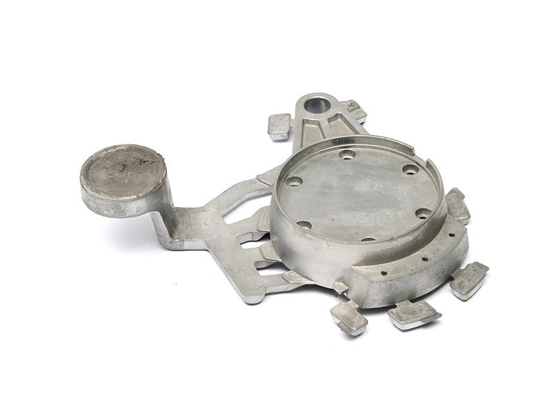
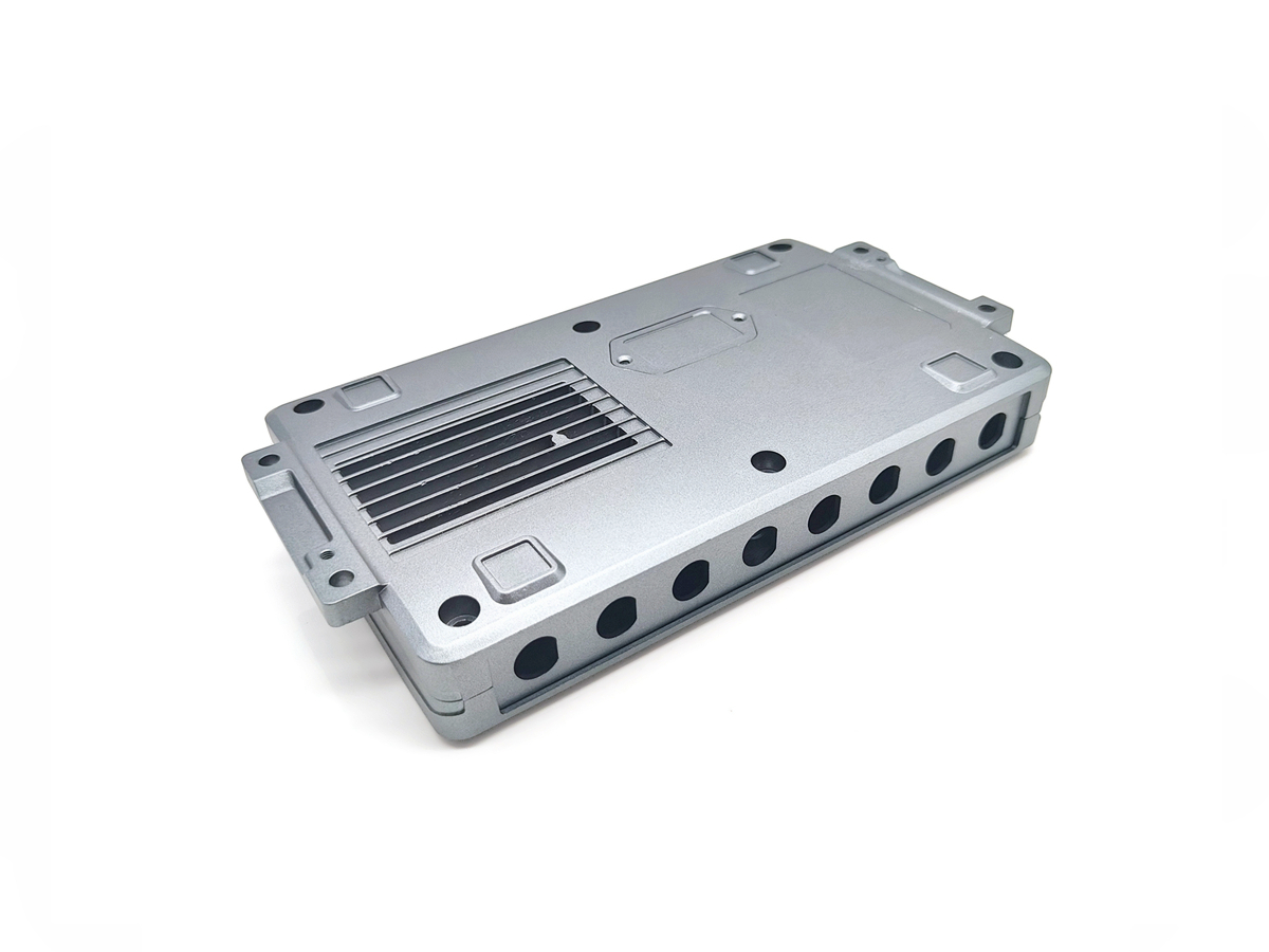
The aluminium enclosure measures 120×90×45 mm, and the alloy is ADC12 to ASTM B85 in the as-cast F temper, a grade pending foundry confirmation. Walls run 2.5±0.2 mm, ribs 2.0 mm, and the finished mass is 380±30 g, all design targets.
Why does the opening face lose its 0.10 mm flatness?
Two loads act before the opening face is cut: the ejector pins and the mill clamp. The pins press the 2.5 mm floor to strip the part, so the floor bows between pins and walls. The mill clamps the opening frame for the top-face cut, closing it before the opening-face cut. The 45 mm side walls carry that bow to the opening, where it reads as a dip, a path pending foundry sign-off.
Neither load leaves a mark on the casting, which is why the fault lands on the mill. A face checked inside the fixture reads flat, and a quote built on it pays a second milling pass while the cause stays in the die.
Which pushes the face out, the ejector pins or the mill clamp?
Ejection and the mill clamp both move the face, and the shape of the gap under the 0.10 mm blade separates them. A face that dips between the pin positions follows ejection, since the pins push the floor away from the die. A face that rocks on one edge follows the clamp, if the fixture loads the frame at a few points.
Because the die carries the ejector layout, a bow traced to ejection costs a die change and a new first article, while a bow traced to clamping costs a fixture change. Which bill lands depends on the cause.
Where does a 2.5 mm floor bend under the ejector pins?
The floor runs 2.5±0.2 mm across 120×90 mm. Pins near the centre bend it most, because the span to the nearest wall is longest.
The die casting layout fixes this before the first shot. A single-cavity die with the gate feeding the floor section and overflow at four corners is a design target pending foundry sign-off; the ejector layout is set against both. Because a pin sits in the die, adding one costs die work and a first article, so the positions belong on the die drawing.
How is 0.10 mm flatness measured on the bench?
A surface plate and a 0.10 mm feeler gauge settle it. The opening face rests on the plate, and the 0.10 mm blade must not enter around the frame. The reading comes from a free part, since a clamped face reads to the fixture.
Because a plate and a blade are bench tools, the check costs bench time rather than a gauge purchase. It belongs in the first-article report with the plate grade and blade named.
Marking 0.10 on the opening face checks the band the lid presses on, while marking the whole frame checks the full perimeter and adds bench time. Attribution follows the cause: a dip between pins is charged to casting, a rock on one edge to machining. That convention is pending foundry sign-off.
| Item | Target (mm) | Allowed range | Checked with |
|---|---|---|---|
| Opening face flatness | 0.10 | Under 0.10, 0.10 blade must not enter | Plate and feeler gauge |
| Floor thickness | 2.5 | 2.5 ± 0.2 | Micrometer |
| Outline at the opening | 120 × 90 | ± 0.3 | Caliper |
What did the 0.15 mm batch change in the process?
An example record from a 200-piece run found six enclosures at 0.15 mm on the opening face, against the 0.10 mm target. A new ejector layout and a stress relief ahead of the opening-face cut were the two changes, and the recheck read 0.06 mm on a free part. That stress relief is pending foundry sign-off.
Because the stress relief is a separate furnace step, it costs a furnace slot and a second setup between casting and milling, so a route that skips it looks cheaper until the face fails the bench check.
Send the drawing with the opening face marked as the datum, the target placed on the face or the frame, plus the batch size, so the quotation separates die work from milling and the bench check.