
Square Watch Case Frame: Zamak 5, 0.9 mm Lugs, Plating
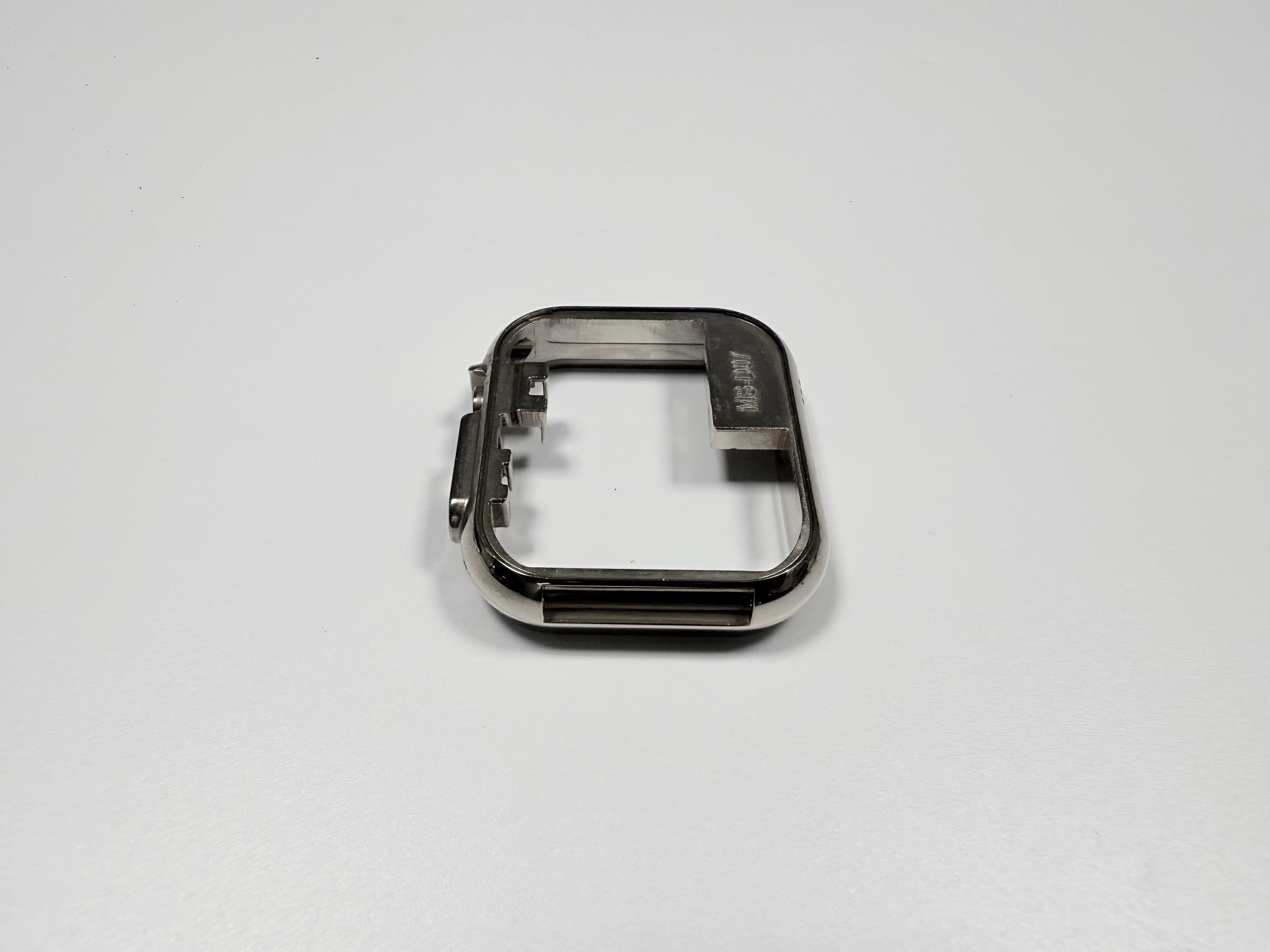
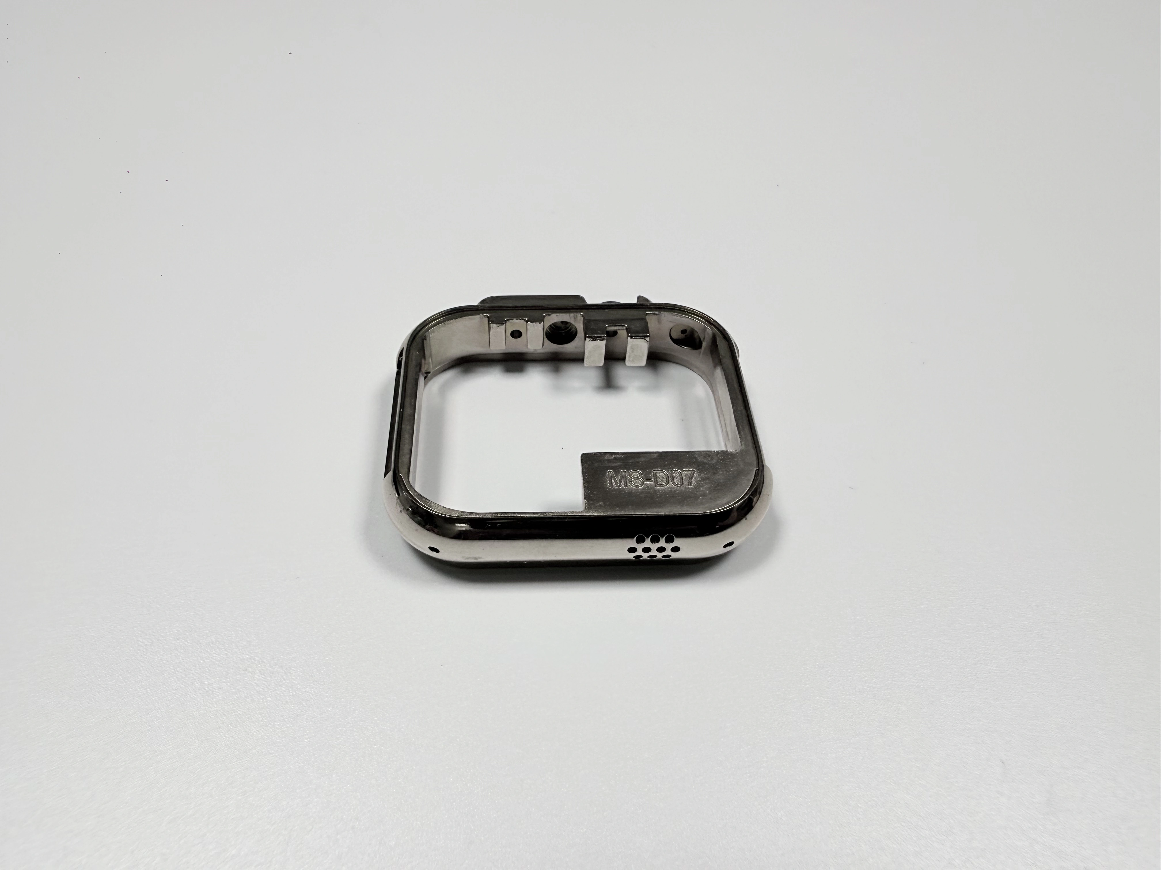
A 38.0×38.0×9.5 mm square watch case middle frame in Zamak 5, 12±1 g. One example record covers this 300-piece batch: nine frames came to inspection with a chipped mouth on a lug bore. A chamfer ahead of the drill and a lower feed at the exit took them to zero on later lots. Zinc die casting set the shape, and the drill exit set the scrap.
Which alloy did the 300-piece run use?
Zamak 5 to ASTM B86 AC41A ran in a four-cavity 8407 tool, then Cu/Ni/Cr plating. The frame carries four interfaces: a 0.03 mm mirror step, a 30.0 mm movement cavity, a Ø3.0 mm crown bore and two Ø1.5 mm lug bores on Ø0.05 mm coaxiality. The wall runs 0.9–1.2 mm, thinning to 0.9 mm at the lugs, where each pin bore is wider than the wall.
Feature | Target (mm) | Allowed band (mm) | Gauge |
|---|---|---|---|
Lug bore, two | Ø1.5 | Ø1.50–Ø1.53 | Ø1.5 plug gauge |
Crown bore | Ø3.0 | Ø3.00–Ø3.05 | Ø3.0 plug gauge |
Movement cavity | 30.0 | 30.00–30.05 | Cavity plug gauge |
Mirror step height | 0.03 | 0–0.03 | Plate and feeler |
Side wall | 0.9–1.2 | 0.9–1.2 | Section check |
Where did the 300 pieces fail?
In that example record, nine of the 300 reached inspection with a chipped mouth at the drill exit, each past the 0.1 mm scrap line. Each frame had already carried the full route. The bore could not be blended back either, because the chip sits on the mouth lip and any blend takes the bore above its upper deviation.
The cause was support at the exit, not the alloy. A Ø1.5 mm drill crossing a 0.9 mm wall breaks into air, and the point pushes the last web out instead of cutting it. No chamfer sat at the exit, and the feed held through the break. Nine in 300 is the scrap allowance a thin-wall quote carries; that loss was booked against casting, yet it starts at the drill exit and the machining line should carry it.
What changed in the drilling step after the first batch?
The programmer changed the hole, not the tool grade. A chamfer now runs ahead of the drill so the point breaks into a supported edge, and the feed drops as the point reaches the exit. Both sit in one CNC program and one setup, which keeps the two lug bores on one axis at Ø0.05 mm coaxiality.
That pass costs cycle time: a second tool and a slower exit, the only lead time this fix adds. The fix is quoted per piece, so its price shows in the machining line.
Which controls held the lug-hole breakout at zero?
Four controls ran after the change. (1) The chamfer stayed in the program, checked on the first piece. (2) The feed drop stayed at the exit. (3) A pre-plate gauge of Ø1.536–Ø1.554 mm screens the bore at the machine, and plating is read to Ø1.50–Ø1.53 mm. (4) First-article sign-off runs the first three before the run starts; the tool shop signs it.
That check costs minutes per lot; a chipped mouth costs the part plus every machining step inside it. The 0.1 mm mouth limit stayed on the inspection sheet as a reject, not a note.
How was the lug hole checked after the drill change?
The bore is read with the plug gauge before plating, against the pre-plate size that carries the coating: Ø1.50–Ø1.53 mm plus a layer on each side, 0.036–0.054 mm, gives Ø1.536–Ø1.554 mm, and it reads Ø1.50–Ø1.53 mm again after plating. The mouth is checked against the 0.1 mm limit, and the two lug axes read Ø0.05 mm on a CMM. The first-article report carries all three readings with their stage, and the gauges sit on the test benches.
The stage matters because the stack moves the bore. Copper, nickel and chromium add 18–27 µm per face, 0.036–0.054 mm across the diameter, so a bore cut to the drawing size finishes below its lower deviation: 1.50 less 0.036–0.054 leaves 1.446–1.464.
Layer | Per face (µm) | Across the bore (mm) |
|---|---|---|
Copper | 8–12 | 0.016–0.024 |
Nickel | 10–15 | 0.020–0.030 |
Chromium | 0.1–0.3 | 0.0002–0.0006 |
Whole stack | 18–27 | 0.036–0.054 |
Bore direction = the per-face value × 2; the sequence is in the plating note.
What does the 300-piece run prove about a 0.9 mm lug wall?
The evidence stops at the drill exit. The wall, the alloy and the bore size did not change between the two lots, so the chamfer and the feed drop moved the count from nine to zero. This case does not prove full-batch yield. A 0.9 mm wall in another alloy, or a bore above Ø1.5 mm, faces a different exit load and needs its own first-off.
Send the 2D drawing with the chamfer, feed note and plating stage, and the next bore can be quoted against all three. A Zamak case with another coating runs the same thin-wall logic.