Aluminum Die Cast Pump Housing Design: Pressure Boundaries, Machining and Leak Validation
Aluminum die cast pump housing design should begin with the fluid system and failure consequences, not with a generic wall-thickness rule. The housing may need to contain pressure, route fluid, support a shaft or actuator, locate mating covers, seal through gaskets or O-rings, carry threaded ports and remain clean after casting and machining. Each function changes tooling access, local section thickness, machining stock, inspection and test planning.
A visually complete casting is not automatically a released pump body. A porosity path can open when a sealing face is machined; an internal dead end can retain blast media or chips; a thick port boss can create a thermal concentration; and a flange can distort when bolted. Buyers need a specification that connects the pressure map to the final machined and assembled condition.
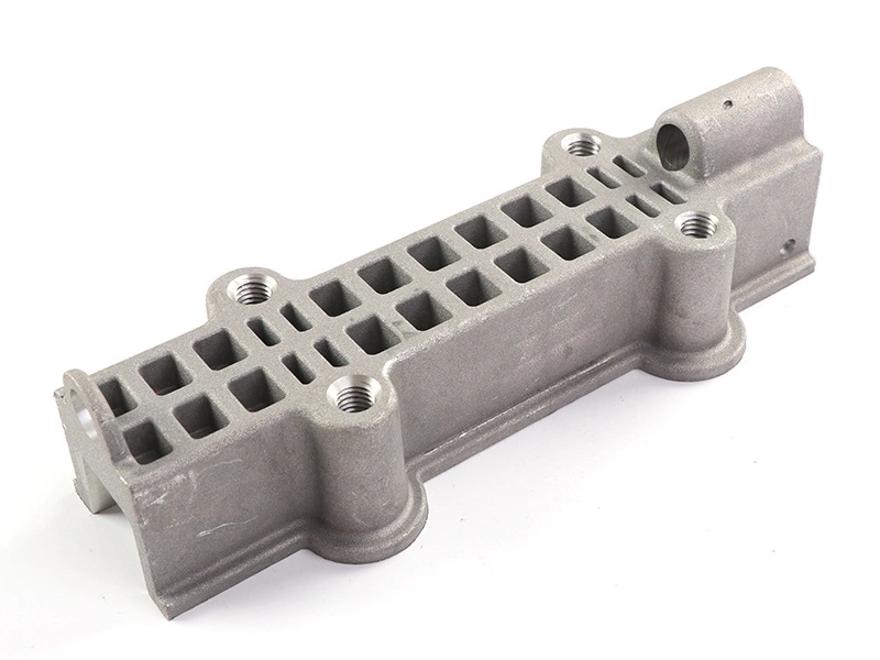
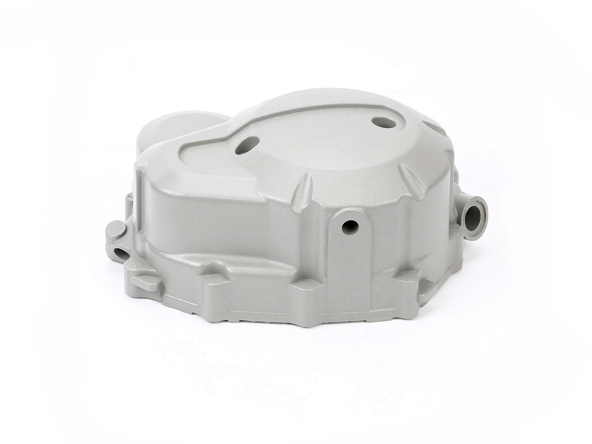
The two images show a chambered aluminum casting with openings and flange-type interfaces. They support a geometry review only. They do not identify a real pump application, material grade, test pressure or achieved leak rate.
Which Fluid-System Inputs Must Be Defined Before DFM?
Start with fluid identity, compatibility, operating and transient pressure, temperature range, flow direction, external loads, vibration, duty cycle, allowable leakage, cleanliness, service life and the consequence of loss of containment. State whether pressure can be applied from more than one port and whether a valve, rotor, impeller, bearing or actuator creates local loads. The customer owns these system requirements.
The casting supplier needs the 3D model and controlled 2D drawing, but geometry alone is insufficient. Mark the fluid-wetted volume, pressure-containing walls, machined openings, seal interfaces, plugged cross-drillings, threaded connections, mounting loads and no-defect regions. Separate nominal operating conditions from proof, burst or other validation requirements defined by the product specification.
Input | Design Decision | Evidence Owner |
|---|---|---|
Fluid and temperature | Alloy/finish compatibility and thermal stack | Product engineering |
Operating and transient pressure | Pressure zone and test definition | System specification |
Allowable leakage | Test method, sensitivity and acceptance | Functional requirement |
Port loads and assembly torque | Boss support and thread strategy | Interface calculation/test |
Cleanliness | Passage access, washing and verification | Product cleanliness standard |
Failure consequence | Inspection depth and traceability | Risk analysis |
Do not let a supplier infer the pressure rating from a similar-looking part. A change in fluid, temperature, port load or seal can invalidate a route that was acceptable for another housing.
How to Map Pressure-Boundary, Functional and Cosmetic Zones
Create a zone map on the model and drawing. Pressure-boundary zones include walls between fluid and atmosphere, walls between two pressure circuits and material below machined seal lands or ports. Functional non-pressure zones can include mounting feet, actuator supports and external ribs. Cosmetic zones control appearance but should not be confused with containment-critical material.
The map should continue through later operations. If machining removes stock from a flange, the final remaining wall is the pressure boundary, not the as-cast surface. A drilled port can intersect a subsurface void or another passage. A threaded plug may make its engagement, spotface and sealing method pressure-critical. Tie each zone to a defect criterion, inspection method and change-review trigger.
Zone | Typical Controls | Release Question |
|---|---|---|
Pressure wall | Minimum section, casting process and leak evidence | Can a connected path reach atmosphere? |
Machined seal land | Stock, flatness, texture and opened-void rule | Will the seal contact continuously? |
Threaded pressure port | Engagement, boss support and sealing system | Can assembly load damage containment? |
Internal passage | Core/slide definition and cleanliness access | Can debris be removed and verified? |
Structural mounting zone | Load path, ribs and fastener interface | Does mounting distort a pressure feature? |
Cosmetic exterior | Appearance master and finish boundary | Is the acceptance visual rather than functional? |
Color coding alone is not control. Put zone definitions in the released data and make sure casting, machining, inspection and assembly teams use the same revision.
How Wall Transitions, Ribs and Port Bosses Affect Casting Risk
Uniform sections generally cool more predictably than abrupt thick-to-thin changes. Pump housings challenge that principle because ports, flange corners, threaded bosses, passage intersections and bearing-type supports concentrate material. Instead of adding solid metal wherever strength is requested, use load paths, cored bosses, blended transitions and proportionate ribs where analysis and tooling access support them.
A rib crossing a thick boss can create a local hot region while also restricting metal flow. A deep thread may drive a large boss even though only a shorter engagement is structurally necessary. A heavy flange can pull a thinner chamber wall during solidification. The design review should compare strength and machining needs with filling, venting, cooling and ejection.
Geometry | Possible Risk | Review Direction |
|---|---|---|
Solid port boss | Hot spot, shrinkage or connected porosity | Core where practical; blend base transition |
Rib-boss intersection | Excess local mass and flow shadow | Stagger, thin or redirect load path |
Heavy sealing flange | Distortion and long cooling region | Use uniform support and machining plan |
Thin wall behind port | Incomplete fill or low remaining section | Check flow, draft, stock and tool access |
Sharp internal transition | Stress concentration and poor flow | Use feasible radii and gradual section change |
Mold-flow analysis for die casting can compare gate direction, air entrapment, fill sequence and thermal concentration before tooling, but simulation inputs and assumptions must be correlated with trial evidence. A colored result image is not a guarantee that every production lot will be sound.
How Internal Passages, Slides and Cores Should Be Planned
Internal passages need a feasible forming direction and a route for tool steel, slides, movable cores or later machining. Identify every undercut, cross-passage, blind pocket and change in section. Confirm withdrawal, draft, shutoff length, slide locking, flash access and how the passage will be deburred and inspected.
Some fluid paths are more reliable when formed partly by casting and completed by drilling, while others become expensive or impossible if a long cross-hole must be plugged. The decision should include tolerance, surface condition, pressure boundary, chip removal and plug reliability. Avoid internal features that cannot be visually accessed, flushed or checked when the cleanliness requirement is critical.
Passage Question | Manufacturing Evidence | Downstream Concern |
|---|---|---|
Can the feature be formed? | Slide/core direction and withdrawal study | Draft, flash and tool life |
Can it be machined? | Tool line, depth and datum access | Breakthrough, burr and chips |
Can it be cleaned? | Flow-through path and drain orientation | Trapped media or wash fluid |
Can it be inspected? | Borescope, flow, imaging or section plan | Blind acceptance assumption |
Can it be sealed? | Plug/interface design and process control | Secondary leak path |
The tool and die making plan should show slides, cores, inserts, shutoffs, ejectors and maintenance access. Trial approval should record passage condition after trimming and machining, not only the external casting.
How Ports, Threads, Inserts and Machining Stock Should Be Specified
Define each port by connection type, mating component, assembly torque or load, sealing method, orientation and service access. Decide whether the thread is machined directly in aluminum, formed around an insert or supported by another interface. Inserts can improve a particular assembly requirement but add placement, bonding, thermal and leak-path controls; they are not an automatic fix for an undersized boss.
Machining stock must clean the as-cast surface at every approved cavity and tool condition without removing excessive pressure-wall material. Map expected cast location against the final port axis and sealing spotface. A one-sided cleanup can leave a thin wall or expose a subsurface region. Stock allowance belongs to the datum and tolerance strategy, not to a generic added offset on every surface.
Feature | Buyer Defines | Supplier Must Return |
|---|---|---|
Threaded port | Thread, engagement, torque/load and seal | Boss, machining and gauge plan |
Insert | Material, position and interface function | Placement, retention and traceability control |
Spotface | Seal/contact diameter and texture | Stock, flatness and burr control |
Drilled passage | Axis, breakthrough and plug requirement | Tool access, chip removal and verification |
Remaining wall | Minimum functional section | Cast/machined distribution evidence |
A relevant pump and valve material example is available in the A413 aluminum die casting application overview. It should be treated as context, not as proof that one alloy or process window fits every fluid, pressure or finish requirement.
How Sealing Faces, Grooves and Datums Work as One System
A gasket land needs controlled flatness, texture, width, bolt-load distribution and freedom from unacceptable opened defects. An O-ring groove adds width, depth, corner, surface and compression relationships defined by the seal supplier and product engineering. The groove, pilot, bolt pattern and mating face should reference a datum system that represents assembly.
Plan the first machining operation to establish durable references. Later seal faces, bores and ports should locate from those references with controlled fixture contact. Clamping must not pull a flange flat for machining if it springs back after release. Measure the free state and, where function depends on bolting, define a repeatable restrained or assembled state separately.
Sealing Element | Critical Relationship | Common Failure |
|---|---|---|
Gasket land | Flatness, texture and bolt pattern | Local gap or surface leak path |
O-ring groove | Section, finish and pilot alignment | Pinch, extrusion or uneven compression |
Port spotface | Perpendicularity to port axis | Uneven washer/seal loading |
Flange bolts | Pattern position and support stiffness | Assembly-induced distortion |
Machining datum | Connection to mating assembly | Good individual dimensions in wrong frame |
Surface texture requirements should identify parameter, cutoff/evaluation method and lay where function requires it. “Smooth finish” is not an inspection standard. Protect sealing faces during deburring, washing, finishing and packaging.
How Porosity Imaging, Leak Testing and Proof Testing Differ
Dimensional inspection, radiography, computed tomography, leak testing and proof testing answer different questions. Imaging can identify internal density indications within method and interpretation limits, but it does not directly prove that a connected leak path exists. A leak test measures flow or pressure behavior under defined conditions. A proof test demonstrates survival at the specified condition; it is not automatically a sensitive leak test or a burst test.
Select inspection from the zone risk and failure consequence. A machined pressure port may need focused examination because cutting can open a path not visible on the as-cast exterior. X-ray inspection for internal flaws can support process understanding when technique, orientation and acceptance are defined. Critical interpretation requires qualified procedures and correlated destructive or functional evidence where appropriate.
Method | Primary Question | Boundary |
|---|---|---|
Dimensional/CMM inspection | Are interfaces in the released geometric frame? | Does not prove containment |
X-ray/CT as specified | Are internal indications present in a risk zone? | Resolution and interpretation limits apply |
Pressure-decay or flow test | Does the assembled test volume exceed leak limit? | Temperature and stabilization affect result |
Liquid leak test | Is leakage visible or measurable with test liquid? | Drying, contamination and sensitivity matter |
Proof test | Does the part withstand the specified load? | Not a universal leak or life test |
The test specification should define medium, pressure or vacuum, ramp, hold, stabilization, temperature, fixture restraint, allowable leakage, calibration, part condition and failure response. Test values come from product engineering; this article does not propose universal settings.
How Cleanliness, Deburring and Impregnation Decisions Are Controlled
Pressure performance can pass while residual chips, abrasive or wash fluid still threaten the system. Define accessible deburring, controlled plug removal, flushing direction, drying and particulate acceptance. Internal thread entrances and intersecting drillings deserve special attention. Validate the cleaning route on worst-access geometry and after the final machining operation.
Impregnation may be an approved secondary process for certain porosity-related leakage conditions, but it should not be used to conceal an uncontrolled casting process or repair geometry outside specification. Product compatibility, cleanliness, cure, rework limit, traceability and revalidation must be defined before use. Keep as-found test data so recurring defect locations can drive casting correction.
Finished housings require protected seal lands, ports and cavities during storage and shipment. Caps and packaging should not shed material into the fluid path or trap moisture. The shipment handoff document should identify the cleanliness state and any cleaning required before final assembly.
Hypothetical Two-Chamber Pump-Housing Release Scenario
Consider a hypothetical two-chamber aluminum die cast housing with an external mounting flange, two machined ports, a gasket land and a drilled cross-passage. The images show geometry that can illustrate such a review, but they are not evidence that the pictured part serves this function.
The team first marks both chamber walls and the material below each machined port as pressure boundaries. Tooling review identifies a thick intersection where a port boss meets the central divider, so the boss and rib transition are revised while preserving required thread support. The slide direction is checked for passage access, and the cross-drilling is given a defined deburring and flushing route.
Machining establishes the mounting face and pilot before cutting the gasket land and ports. Trial parts are measured free state and in the defined assembly restraint. Dimensional results, internal inspection selected from the risk analysis, cleanliness data and the customer-defined leak/proof tests are reviewed on the same serialized samples. No result is assumed in this scenario.
Gate | Required Output | Reason to Hold Release |
|---|---|---|
DFM gate | Zone map, tool access and transition review | Unformed or uncleanable passage |
Tool trial | Fill, trim, stock and internal-feature evidence | Unstable stock or indication in critical zone |
Machining trial | Datum, seal and port report | Springback or inadequate remaining wall |
Functional trial | Defined leak/proof and cleanliness results | Unexplained failure or method disagreement |
Pilot release | Cavity/lot capability and traceability | Results cannot be linked to process conditions |
This scenario illustrates the evidence chain. It does not claim a Neway customer case, pressure capability, certification or test result.
What to Include in an Aluminum Pump-Housing RFQ
Provide STEP or X_T data, a controlled 2D drawing, fluid and compatibility requirements, operating and transient conditions, pressure-zone map, alloy requirement or performance basis, quantity, service life, mating parts, seal supplier data, thread and port loads, finish, cleanliness, inspection and test specifications. Identify CTQs and the consequence of a leak.
Request DFM covering fill/vent direction, thick sections, slides/cores, parting and ejection, machining stock, fixture datums, seal-face control, passage cleaning and test correlation. The mass-production quality control plan should preserve cavity, tool, machine, machining and functional-test traceability rather than reporting only a final pass/fail count.
RFQ Package | Buyer Input | Supplier Response |
|---|---|---|
Functional envelope | Fluid, pressure, temperature, loads and life | Assumptions and process risks |
Zone map | Pressure, seal, cleanliness and cosmetic zones | Inspection and control mapping |
Tooling | Allowed splits and design constraints | Gate, vent, slide, core and maintenance concept |
Machining | Final datums, tolerances and surfaces | Stock, fixture and gauge plan |
Validation | Leak, proof, cleanliness and report standard | First-article and pilot evidence matrix |
Change control | Notification and reapproval rules | Traceability and revalidation triggers |
Use design engineering support only after the product inputs are explicit. A manufacturable pump-housing-type casting is released when pressure boundaries, machining, sealing, cleanliness and functional evidence agree on the same drawing and part revision.
How Change Control Protects Repeat Pump-Housing Production
Changes to alloy source or condition, die inserts, gates, vents, cooling, slide or core geometry, machining stock, datum targets, cutters, fixtures, washing, impregnation, seal supplier, test equipment or packaging can affect containment. Classify changes by the zones and characteristics they can influence. A tooling repair far from a fluid wall may need limited confirmation; a port-core or seal-land change needs focused revalidation.
Retain approved first-article data, boundary samples where useful, test-method records and traceability links. When a leak occurs, preserve the as-found part and identify whether the path is through cast material, a machined surface, a thread, a plug, a seal or the test fixture. Reworking before locating the path destroys evidence and encourages the wrong correction.
The production standard should define reaction limits for trends, not only final rejects. Movement in leak rate, machined stock, pressure-decay stabilization or defect location can signal drift before failures exceed acceptance. Review trends by cavity and process route so a stable population does not hide one worsening source.
FAQ
How Should a Pump Housing Pressure Boundary Be Marked on the Drawing?
Which Port and Boss Features Create Hot-Spot Risk in an Aluminum Pump Housing?
How Should Internal Passages Be Designed for Casting and Final Cleaning?
What Machined Features Usually Control Pump-Housing Sealing and Assembly?
How Should Leak, Proof-Pressure and Dimensional Evidence Be Released Together?