In-Depth Mold Flow Analysis for Better Die Casting Precision
Introduction
In die casting, the precision of molten metal flow into complex mold geometries directly affects part quality, dimensional accuracy, and defect rates. Without proper planning, issues like air entrapment, cold shuts, shrinkage porosity, and incomplete fills can compromise performance and increase scrap.
Mold flow analysis offers a virtual solution by simulating the behavior of molten aluminum, zinc, or copper alloys during the filling and solidification stages. At Neway, we integrate in-depth mold flow simulation into our die design process to validate part geometry, optimize gate and runner layouts, and ensure defect-free castings before producing tooling.
What Is Mold Flow Analysis?
Mold flow analysis is a computer-aided simulation process that models the injection of molten metal into a die casting mold. Using the part’s 3D CAD model and detailed process parameters, the software predicts how metal fills the cavity, where air may be trapped, how heat is dissipated, and where solidification begins.
Core Simulation Outputs
Parameter | Description |
|---|---|
Fill Time | Duration for complete cavity fill |
Flow Front Behavior | Pattern and direction of molten metal during injection |
Air Entrapment | Areas where gases are likely to become trapped |
Temperature Distribution | Hot spot detection for shrinkage porosity prediction |
Solidification Rate | Cooling behavior and potential cold shut zones |
Gate Velocity | Speed of metal at the gate and its impact on mold erosion or flash |
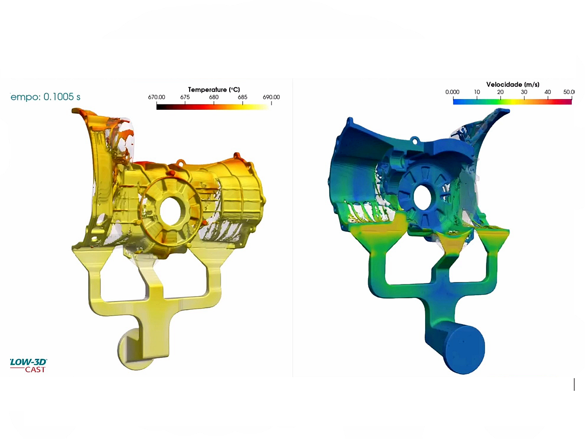
Advanced simulation tools like MAGMASOFT, FLOW-3D Cast, and ProCAST are used to replicate real-world casting conditions accurately.
Why Mold Flow Analysis Matters
Benefit | Description | Value |
|---|---|---|
Defect Prevention | Identifies risks like porosity, cold shuts, and misruns | Minimizes scrap and improves yield |
Gate/Riser Optimization | Fine-tunes location and size of gates and vents | Improves metal flow and part filling balance |
Cooling Strategy Validation | Verifies thermal management and cycle time reduction | Reduces residual stress and tool wear |
Dimensional Accuracy | Ensures uniform solidification and shrinkage control | Improves consistency and reduces warping |
Faster Tooling Validation | Resolves issues before cutting steel | Saves time and tooling costs in early development |
In one case study, mold flow simulation helped optimize the A380 aluminum motor housing gating system, reducing internal porosity by over 60% and cutting tooling iteration cycles from three to one.
Key Inputs for Accurate Mold Flow Simulation
To ensure meaningful results, simulations are based on precise input data:
3D CAD Model: High-resolution geometry with draft, fillets, wall thicknesses
Material Properties: Viscosity, thermal conductivity, specific heat, solidus/liquidus temperatures for alloys like AlSi12 or Zamak 5
Process Parameters: Injection pressure, fill speed, die temperature, shot sleeve velocity
Cooling System Design: Layout of cooling channels and chill zones
Runner/Gate Design: Entry locations, cross-sectional areas, venting paths
Simulations are adjusted iteratively to reflect real-world production settings as closely as possible.
Mold Flow Analysis Applications
Mold flow analysis supports all types of high-pressure and gravity die casting processes and is especially useful for:
Thin-Walled Parts: Ensures complete filling in tight geometries
Complex Geometries: Validates moldability of intricate designs
Large Castings: Prevents unbalanced flow and excessive shrinkage
Multi-Cavity Dies: Confirms uniform flow across all cavities
High-Speed Production: Supports optimized gate design to avoid turbulence and soldering
It is widely used for components such as engine blocks, housings, lighting structures, brackets, and structural reinforcements.
Integration with Die Design and Manufacturing
Neway’s comprehensive tooling design and production workflow includes mold flow analysis. It works in conjunction with:
CAD and CAM modeling: Seamlessly integrates with parametric part and die design
Thermal and stress FEA: Identifies combined mechanical and thermal distortion
Material selection: Ensures the chosen alloy behaves as expected under high-pressure injection
Surface treatment: Supports post-casting polishing, coating, or machining planning
We use mold flow feedback to refine tool paths, cooling strategies, and ejector designs before final mold cutting.
Deliverables and Reporting
Clients receive a detailed simulation report that includes:
3D visualizations of flow behavior, temperature fields, and solidification progress
Critical defect zones with cause analysis
Suggested gate, runner, or part geometry modifications
Material-specific recommendations
Cycle time and energy efficiency estimates
Reports are delivered in PDF format with annotated visuals and optional animation files for internal design reviews or stakeholder presentations.
FAQs
What die casting defects can mold flow analysis help prevent?
How accurate is mold flow analysis compared to physical testing?
Can mold flow be used on zinc, copper, and magnesium alloys?
Do I need to redesign my part after a mold flow study?
How long does a mold flow analysis typically take for a complex part?