Advanced Performance Simulation for Reliable and Optimized Component Design
Introduction
In today’s engineering-driven industries, product reliability, precision, and speed to market are not optional—they are essential. Advanced performance simulation, using techniques such as Finite Element Analysis (FEA), allows engineers to validate and optimize component behavior before any material is cut or cast. This digital-first approach enables faster design iteration, lower prototyping costs, and more robust, high-performance parts.
At Neway, we integrate advanced simulation into our product development workflow to ensure that every component we design or manufacture meets functional requirements under mechanical, thermal, or fatigue-related stress. From CNC machined parts and die castings to injection molds and structural assemblies, our simulations empower data-driven engineering decisions.
What Is Performance Simulation?
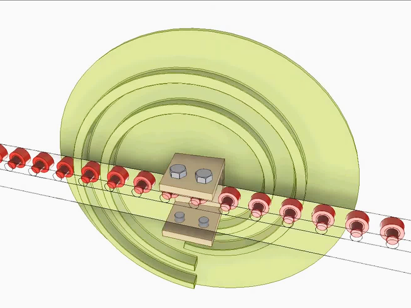
Performance simulation refers to the digital evaluation of how a component or assembly behaves under operating conditions using numerical models. This may include structural loads, temperature changes, vibration, wear, or fluid pressure. The most common method used is Finite Element Analysis (FEA), which divides a model into small elements to calculate stress, strain, deformation, and other critical parameters.
Core Simulation Types
Simulation Type | Description | Typical Use Case |
|---|---|---|
Static Structural | Analyzes stress and displacement under constant loads | Mounting brackets, housings, supports |
Transient Thermal | Models heat transfer over time | Heat sinks, molds, electronic enclosures |
Modal & Vibration | Determines natural frequencies and resonant modes | Aerospace parts, rotating shafts |
Fatigue Life | Estimates part failure under cyclic loads | Automotive arms, sensor mounts |
Nonlinear Contact | Evaluates interactions between assembled parts | Clamps, gaskets, multi-body systems |
Key Inputs and Engineering Assumptions
The accuracy of any simulation is determined by high-quality input parameters:
Material Data: Young’s modulus, Poisson’s ratio, yield strength, thermal conductivity
Boundary Conditions: Constraints, supports, contact interfaces
Loading Conditions: Pressure, torque, force vectors, thermal flux
Mesh Quality: Finer mesh in high-stress areas, convergence control
Environment: Ambient temperatures, vibration spectra, load cycles
Typical materials include aluminum (E = 70 GPa, yield strength ~250 MPa), stainless steel (E = 200 GPa, yield ~500 MPa), and tool steels like H13 and D2 for thermal applications. All data are aligned with ASTM, ISO, or SAE standards depending on the simulation’s end-use.
Benefits of Performance Simulation
Benefit | Engineering Value | Business Impact |
|---|---|---|
Early Design Validation | Detect failure modes before prototyping | Reduce physical test costs by up to 60% |
Lightweighting | Remove unnecessary material without compromising strength | Lower machining time and material usage |
Thermal Optimization | Control hot spots and stress due to expansion | Enhance product lifespan and dimensional stability |
Vibration Control | Predict natural frequencies and avoid resonance | Ensure safe, quiet operation |
Durability Forecasting | Simulate fatigue and wear under real-world cycles | Improve product reliability and warranty assurance |
In a recent case, fatigue simulation helped a client redesign a sensor bracket for off-road vehicles. Geometry was modified to increase fatigue life from 400,000 to over 1 million cycles, extending component service life without increasing material cost.
Typical Applications of Simulation at Neway
Advanced performance simulation is used in a wide range of industries and part types:
CNC Machined Components: Structural analysis of fixtures, tooling, and machine parts
Aluminum Die Castings: Thermal and stress validation for engine housings, heat-dissipating covers
Tool and Die Systems: Thermal expansion and cyclic loading prediction
Medical Devices: Load-bearing evaluations and life testing for implants and instruments
Electronics and Enclosures: Thermal and vibration resistance analysis
Simulation data directly informs geometry changes, material selection, and manufacturability decisions, especially for high-volume production environments.
Integration with CAD, CAM, and Production
Simulation results are not standalone—they integrate directly into Neway’s broader development and manufacturing ecosystem:
CAD Modeling: Clean, parametric designs ready for meshing
Material Selection: Tailored to the thermal, mechanical, or fatigue loads required
CNC Machining: Simulated models are transitioned into manufacturing with tolerance control
Prototyping and Validation: Physical builds confirm digital predictions before mass production
DFM and Optimization: Reduce cycle times and improve tooling life using simulation-guided geometry
This integrated workflow accelerates time-to-market while ensuring performance and manufacturability go hand-in-hand.
Deliverables and Reporting
Simulation results are documented in a comprehensive engineering report that includes:
Color-coded stress and strain distribution maps
Displacement and deformation visuals
Fatigue life plots and safety factor zones
Thermal maps and transient time-temperature curves
Design feedback and recommended changes
File compatibility with SolidWorks, ANSYS, STEP, and Parasolid
All simulations follow documented industry practices with results validated against empirical benchmarks or known boundary conditions.
FAQs
What file formats are accepted for performance simulation?
Can simulation help reduce physical prototypes and testing costs?
How accurate are simulations for fatigue and thermal performance?
Do you offer iterative design optimization based on simulation results?
Is simulation suitable for multi-material or composite components?

