Comprehensive Structural and Thermal Analysis for High-Performance Components
Introduction
High-performance components are often exposed to extreme mechanical loads, elevated operating temperatures, and prolonged fatigue cycles. Failure is not an option, from aerospace brackets and electric motor housings to injection molds and heat exchangers. Comprehensive structural and thermal analysis is critical in the early design stages to ensure reliability and reduce costly prototyping.
At Neway, we leverage finite element analysis (FEA) and thermal simulation to predict component performance accurately under real-world stress and thermal loading. This data-driven approach minimizes failure risk, optimizes material use, and accelerates product development across automotive, aerospace, industrial automation, and die casting industries.
What Is Structural and Thermal Analysis?
Structural analysis evaluates a component’s response to mechanical forces like tension, compression, and vibration, while thermal analysis models heat transfer and the effects of thermal expansion or cycling. These simulations are often coupled in high-performance designs where mechanical stress and temperature changes interact dynamically.
Common Simulation Types
Simulation Type | Description | Use Case |
|---|---|---|
Linear Static | Analyzes stress, strain, and displacement under constant loads | Load-bearing structural components |
Transient Thermal | Tracks temperature variation over time under changing heat loads | Mold inserts, exhaust systems |
Steady-State Thermal | Models thermal equilibrium conditions | Enclosures, radiators, cooling blocks |
Coupled Thermal-Structural | Simulates combined mechanical stress and thermal expansion | Die casting tools, brake discs |
Modal/Fatigue | Calculates vibration modes and fatigue life | Aerospace mounts, rotating shafts |
Industry-standard software platforms such as ANSYS, Abaqus, and SolidWorks Simulation are used for accuracy and traceability.
Key Engineering Standards and Parameters
Our simulations adhere to global standards for structural and thermal validation:
ASME Y14.5 for geometric dimensioning and tolerancing (GD&T)
ISO 13715 for edge conditions and stress riser management
ASTM E8 and ISO 6892 for material tensile data input
EN ISO 527-1 for plastics and composite simulation inputs
RoHS and REACH compliance for material compatibility assessments in regulated industries
Input parameters are selected based on real material data, including:
Young’s modulus (E): 70 GPa for Aluminum 6061-T6
Yield strength: 250 MPa (AlSi12), 450 MPa (H13 tool steel), up to 930 MPa (Ti-6Al-4V)
Thermal conductivity: 167 W/m·K for Aluminum 6061, 24 W/m·K for Stainless 304
Coefficient of thermal expansion: 23.1 µm/m·K for A380 aluminum
Why Structural and Thermal Analysis Matters
Performance Objective | Engineering Impact | Outcome |
|---|---|---|
Strength & Stiffness | Verifies stress levels < 70% of yield strength | Prevents plastic deformation or fracture |
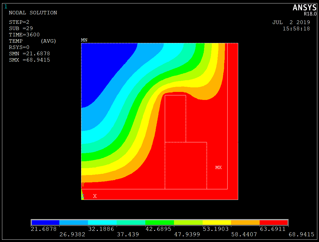
Heat Management | Predicts max temperature, thermal gradients, hotspots | Ensures material integrity under heat |
Vibration Control | Identifies resonant frequencies and mode shapes | Prevents fatigue due to vibration |
Dimensional Stability | Models thermal expansion and mechanical creep | Ensures fit and function over lifecycle |
Design Optimization | Reduces unnecessary material and enhances support | Increases efficiency and reduces weight |
In one case, FEA helped redesign a CNC-machined aluminum mounting bracket. Modifying rib geometry and reducing overbuilt regions reduced part mass by 22%, while maintaining a safety factor of 2.1 under static loading.
Applications in Manufacturing and High-Performance Industries
Structural and thermal analysis is used across Neway’s service offerings for:
CNC Machined Parts: Evaluate brackets, tooling, machine frames
Die Casting: Assess thermal fatigue in A380, AlSi12, or Zamak 3 components
Injection Mold Components: Predict thermal distortion in steel cores and hot runners
Thermal Control Systems: Simulate heat dissipation in copper or aluminum cooling plates
Mechanical Assemblies: Fatigue analysis for long-term cyclic loads (e.g., robotics, aerospace fixtures)
These simulations are validated against prototype results or benchmarked against industry limits for allowable deflection (<0.1 mm), stress limits (<75% of yield), or thermal distortion (±0.05 mm in fit-critical regions).
Integrated Engineering Workflow
Structural and thermal analysis is tightly integrated into Neway’s digital engineering pipeline:
3D CAD modeling: Simulation-ready parametric geometry
Material selection: Matched to mechanical and thermal loads
Reverse engineering: Apply FEA to legacy parts for performance upgrades
Machining and prototyping: Validate simulation assumptions with real-world results
Tool and die design: Optimize cooling layouts and reduce cycle times
Simulating in parallel with product development reduces design iterations and improves first-pass production success.
Deliverables and Reporting
Clients receive a detailed simulation report including:
Full-color stress, strain, temperature, and displacement maps
Safety factor and fatigue life assessments
Thermal gradient distribution and hotspot locations
Geometry recommendations (e.g., wall thickness, fillet size, rib placement)
Validation notes aligned with ISO and ASME guidelines
All results are delivered in editable formats upon request and accompanied by a PDF report for quality assurance and stakeholder review.
FAQs
What’s the difference between steady-state and transient thermal analysis?
How accurate are FEA simulations compared to real-world test results?
Can you analyze both metals and engineering plastics?
What information do you need to begin a simulation?
How does thermal expansion affect part fit or performance?