Can High-Pressure Die Casting Hold 1.5 mm ADC12 Walls?
High-pressure die casting can hold a 1.5 mm ADC12 wall, but the wall comes as a package: vacuum die casting, one cavity, gate and overflow placed for the thin section, and a machined datum after T6. Thin wall aluminum die casting at this thickness is a filling window, and it closes when any of the four moves.
What 1.5 mm Changes in the Fill
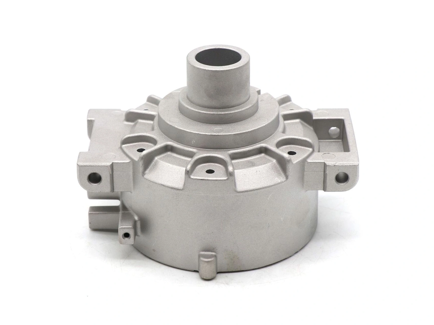
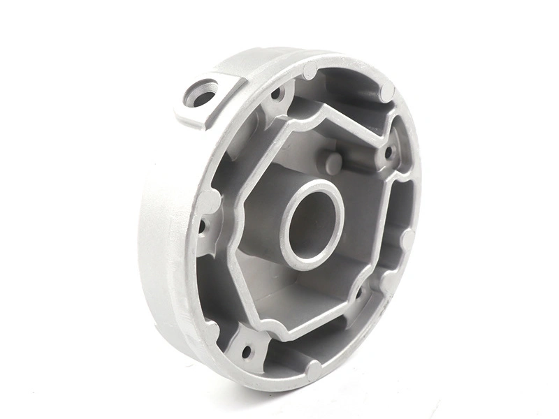
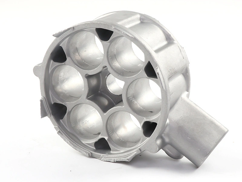
At 1.5 mm the metal freezes while the cavity is still filling. This frame runs 320×180×90 mm at 1.2–1.8 kg, so the last point to fill sits far from the gate. Gate speed rises to reach it, and the jet folds more air into the cavity.
The wall is a design target for this frame, confirmed against the die and the machine that will run it. Catalogs list wall ranges, not a release for a 1.5 mm load-bearing frame. A quote built on the wall callout covers the wall and misses the fill.
Vacuum, One Cavity, and Where the Gate Goes
Vacuum die casting pulls air from the cavity before the shot, so less gas is left to form porosity in a wall that cannot feed it out. One cavity keeps that condition identical on every shot: one gate, one overflow path, one last place to fill. More cavities split the tool cost and the venting.
The gate lands in the thick joint boss, and the overflow sits at the far end of the 1.5 mm wall, so the cold front leaves the cavity instead of stopping there. The die is H13, cut for this wall from the start; vacuum die tooling adapted from a thicker part keeps the old gate position, and the far end runs cold.
Vacuum does not rescue a gate placed on the wall itself: the jet washes the 1.5 mm section and the front splits.
Cold Shut and Short Fill: What Shows Up
A cold shut is two flow fronts meeting without welding. It reads as a line on the as-cast surface, usually at the last place to fill, and can sit inside a boss where no one looks. Short fill is a feature that never formed.
Paint hides the line, and machining can remove it, so the acceptance is X-ray/CT with the slice placed at the thin-wall far end, read against the as-cast surface. Appearance inspection passes a frame whose cold shut sits under the finish.
T6 does not repair either defect. A solution treatment at 490–510 °C does not weld a front that never bonded, and it adds blister risk from trapped gas.
Why the 1.5 mm Wall Cannot Be the Datum
A 1.5 mm as-cast wall moves when it is clamped. It carries draft, and its surface varies along the flow, so a datum there reads differently at every setup. The joint seat and actuator faces are machined; the ±0.02 mm assembly face, the 0.03 mm flatness, and the ±0.02 mm hole position are design targets on the machined face.
The route fixes the order: vacuum die casting, degate, T6, straightening, CNC. Straightening sits between the furnace and the cut because quench distortion moves the whole frame, and the cut removes a small allowance rather than pulling a twisted frame straight. A datum on the as-cast wall makes the CMM result follow the clamp pressure, so ±0.02 mm measures how the part was held.
What to Put in the Drawing and the RFQ
A drawing that says 1.5 mm wall and ADC12 leaves the process to the supplier, which is where the wall is won. Write the wall as a target, then the conditions that repeat it: ADC12 to ASTM B85, vacuum die casting, H13, one cavity, gate and overflow position, CT acceptance at the far end.
Strength and heat treatment go on the same sheet as targets. 400 MPa is the tensile target after T6, and the drawing should call it that. The T6 window is 490–510 °C solution with 150–170 °C aging, its feasibility confirmed by the foundry before the PO.
Callout | Value (unit) | Drawing wording |
|---|---|---|
Wall thickness | 1.5 mm | Design target |
Alloy | ADC12 to ASTM B85 | Grade plus standard |
Casting route | Vacuum die casting, one cavity, H13 | Process requirement |
Fill acceptance | X-ray/CT at the far end | Name the slice |
Assembly face | ±0.02 mm, flatness 0.03 mm | Target, machined face |
Tensile target | 400 MPa after T6 | Target, not measured |
T6 window | 490–510 °C, 150–170 °C | Foundry to confirm |
Send the drawing with the datum callout, the CT slice location, and the 1.5 mm marked as a target. A quote that answers all three can be compared; one that answers only the wall cannot.