Does Type III hard anodizing cause dimensional changes in parts?
Yes. Type III hard anodizing changes part dimensions because aluminum is converted into an oxide layer that develops relative to the original surface. External surfaces tend to build outward, holes and slots tend to close, and threads are affected on several flanks. The actual growth fraction and local thickness must be established for the specified alloy, coating requirement, geometry and qualified process; a universal 50/50 rule is not a sufficient tolerance plan.
Translate coating build by feature
Feature | Likely dimensional effect | Planning action | Acceptance |
|---|---|---|---|
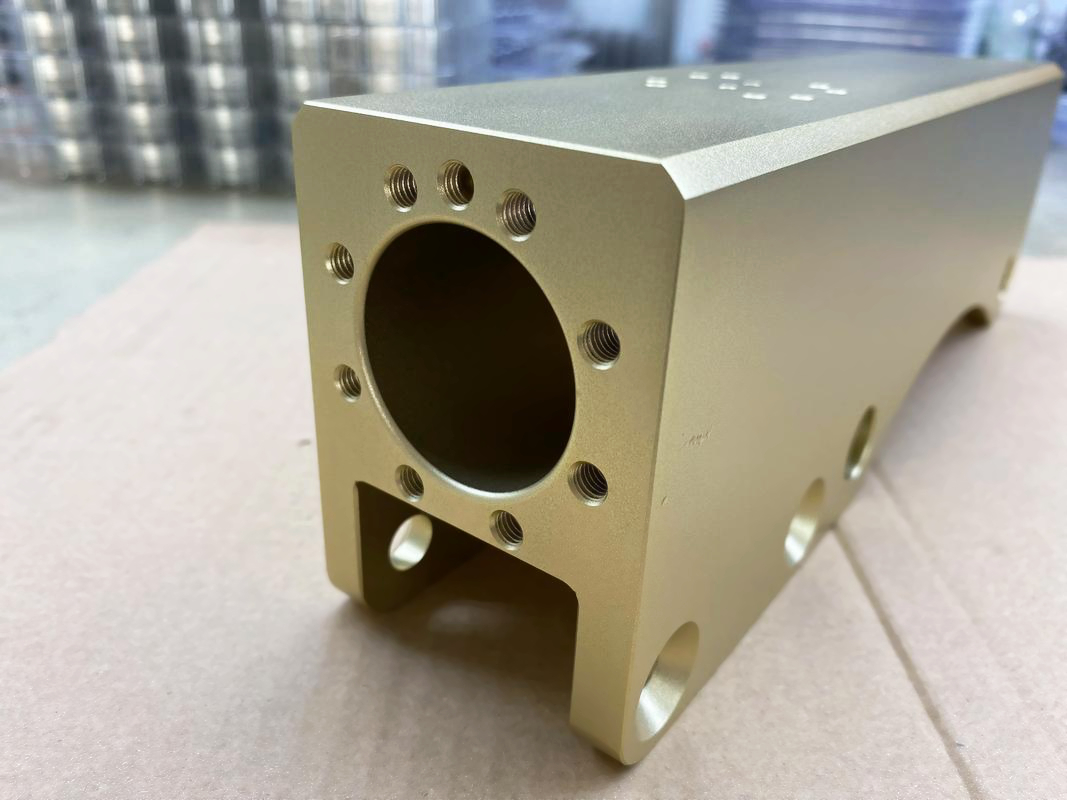
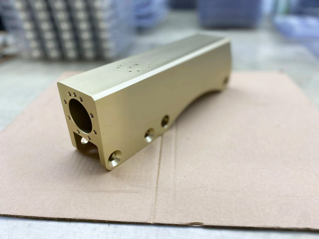
External width or diameter | Opposing coated surfaces increase the overall size | Machine pre-finish size with processor growth allowance | Measure after final seal/post-treatment |
Hole, bore or slot | Coating on opposing surfaces reduces opening | Provide allowance or mask if function permits | Functional gauge and local coating evidence |
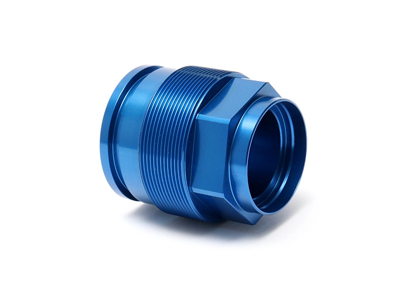
Internal/external thread | Flank coating changes pitch-diameter fit and can bridge roots | Use approved pre-finish limits, masking or post-finish thread strategy | Specified finished thread gauge |
Sharp edge | Local electric field and fragile geometry can change build or cause burning/chipping | Add appropriate radius and review contact/racking | Visual plus functional edge criteria |
Masked boundary | Transition may have a step, taper or small bare band | Dimension mask line and keep it out of sealing/wear zones | Boundary location and final function |
Why the growth is not one fixed ratio
The oxide forms by consuming substrate and developing a coating. Alloying elements, bath conditions, current density, time, dissolution, sealing and local geometry affect the result. Processor data may support a planning factor for a qualified alloy and route, but the drawing should control final dimensions and coating requirements rather than encode a generic internet ratio.
Current density is not uniform on every geometry. Edges, recesses, deep bores, blind holes, rack contacts and shielded surfaces can receive different coating build. A thickness reading on an accessible flat surface does not automatically represent a thread or narrow slot. Review locations with the anodizing processor before final machining limits are released.
Build a finished-state tolerance stack
Start from the assembly limit. Allocate variation among pre-anodize machining, coating thickness/growth, sealing or post-treatment and measurement. If the required final tolerance is narrower than the combined process variation, change the design, mask the feature, alter the fit or use an approved finishing operation. Tightening the pre-anodize machining tolerance cannot remove coating variation.
State whether drawing dimensions apply before or after anodizing. For finished dimensions, give the machinist a controlled pre-finish table linked to the coating processor's qualified growth data. Do not leave the shop to infer whether nominal CAD represents bare metal or final oxide.
Datums also matter. A fixture locating on a surface that later receives hardcoat may shift a related feature. Inspection should use the final datum scheme and condition parts consistently before measurement. Thin sections or long parts may change through handling or thermal cycles, so separate coating build from distortion.
Threads, bearings and electrical contacts
Threads can be masked, cut to a pre-finish allowance or processed and accepted with a finished gauge, depending on design and specification. Chasing a thread after anodizing removes the oxide from selected surfaces and can damage adjacent coating. That may be acceptable only when the drawing explicitly permits it and corrosion, wear or electrical requirements are reassessed.
Bearing and sliding lands need both dimension and surface-function control. Hardcoat roughness, sealing and mating material affect friction. Grinding or honing after hardcoat may be used in a qualified route, but it changes coating thickness and must leave enough sound oxide. Sandblasting is not a precision method for restoring a hardcoated fit.
Mask electrical contacts and bonding surfaces where oxide insulation is undesirable. Define the boundary because coating creep or a bare transition can affect contact area. Verify resistance or bond function on the finished assembly rather than relying only on a visual mask check.
Measure both coating and part
Use a coating-thickness method suitable for the substrate and geometry, with calibration and agreed locations. Eddy-current measurement can be useful on accessible aluminum surfaces; cross-sectioning provides local destructive evidence; weight methods answer coating-mass questions. The governing specification determines acceptable methods and sampling.
Then inspect the actual finished features: bore gauge, thread gauge, coordinate measurement, profile or functional assembly as appropriate. A coating report does not prove fit, and a passing fit does not prove minimum coating in a wear zone. Both claims need evidence.
The broader Type III tolerance guide helps buyers map these controls before RFQ.
Buyer answer
Provide alloy/temper, governing specification and revision, coating thickness and seal, coating/masking map, finished datums and tolerances, threads, fits, rack restrictions and inspection methods. Ask the processor for qualified growth data and thickness capability on representative geometry. Validate all cavities or manufacturing sources that can change substrate condition.
Type III dimensional change is manageable when it is treated as a feature-specific manufacturing stack. It becomes a problem when a fixed outward-growth percentage is applied to the whole drawing. Control the final part, use approved pre-finish allowances and verify coating plus fit after the complete anodizing route.