Aluminium Heat Sink Material: Choosing Casting Alloys for Thermal Performance and Production
Selecting an aluminium heat sink material is not a contest for the highest conductivity number. A production heat sink must carry heat through an actual alloy lot, fill a cast fin field, survive ejection and assembly, present a controlled base to the thermal interface material, resist its environment and meet a volume cost target. The American spelling, aluminum heat sink material, describes the same sourcing problem.
The critical path runs from the heat source through the interface material, machined or as-cast base, alloy body, fin roots, fins and surrounding air. A better value in one material table cannot compensate automatically for an unfilled fin, a porous interface region, a distorted base, excessive coating under the contact area or a test performed under different mounting conditions.
Buyers therefore need a linked approval process. First compare data generated under compatible standards and material conditions. Then translate the shortlisted alloy into gate direction, flow length, fin geometry, machining stock and finish boundaries. Finally, verify the finished part under a controlled thermal test and retain the alloy certificate, dimensional evidence, test setup and revision record for later lots.
What Makes an Aluminium Alloy Suitable for a Heat Sink?
A useful alloy decision has six dimensions: thermal transport, castability, mechanical integrity, environmental resistance, machinability and volume economics. These dimensions interact. High fluidity can support a long, narrow flow corridor, but the chemistry and process window still need to meet strength, corrosion, machining and thermal requirements. A strong base can hold fastener load, yet added mass or difficult filling can reduce the production advantage.
Start with the finished assembly rather than an alloy name. Define heat input, temperature limit, ambient, airflow, envelope, mounting load and interface material. The drawing then turns that duty into base, fin, datum, finish and acceptance requirements.
Decision Dimension | Material or Part Requirement | Manufacturing Consequence | Buyer Evidence |
|---|---|---|---|
Thermal transport | Conduct heat through the certified alloy and complete base-to-fin path | Controls base section, fin area and sensitivity to local discontinuities | Condition-matched datasheet, actual alloy certificate and controlled part test |
Castability | Fill the intended fin height, spacing, draft and flow length | Drives gate direction, overflow, venting, die thermal balance and trial window | Fill review, trial parts and last-to-fill/air-escape evidence |
Strength and stability | Hold mounting load and retain geometry through ejection, machining and assembly | Affects fin damage, boss design, fixture support and base distortion | Applicable material data plus dimensional and functional checks on parts |
Corrosion and finish | Survive humidity, contaminants, galvanic contact and appearance requirements | Changes pretreatment, coating, masking, contact resistance and tolerance stack | Actual-alloy finish trial and application-specific exposure plan |
Machinability | Create the thermal interface, holes and datums without unacceptable breakout | Sets stock, tool access, fixture scheme and porosity reaction rules | Machined sample, flatness/roughness record and opened-porosity disposition |
Volume economics | Meet annual demand, yield, cycle, secondary-operation and quality cost targets | Connects alloy availability with scrap, machining time, finish and inspection | Costed process route with assumed volume, yield boundary and change controls |
Do not rank these six factors independently. Weight them for the application, identify non-negotiable failure limits and compare only candidates that can satisfy those limits. The supplier workflow should return an alloy designation and governing specification, certificate requirements, fin-fill plan, machining concept, thermal test condition and a list of changes that require revalidation.
Why Pure-Aluminum Conductivity Is the Wrong Comparison
Pure aluminum is a poor quotation reference for A380, ADC12, A360 or A413-type casting alloys. Alloying elements and microstructure support casting and mechanical behavior but also change thermal transport. Published values may refer to high-purity metal, wrought product, a laboratory coupon, a particular condition or a temperature unlike the finished casting's service state. Substituting that number for a die cast part creates false confidence.
Even two values carrying the same units may not be directly comparable. One source may report a typical value, another a minimum, and a third a calculated estimate. Sample form, heat history, composition window, porosity, orientation, test temperature and method can differ. A vendor table without a cited specification and condition is useful for screening only, not final acceptance.
Data Field | Why It Changes Comparability | Acceptable Use | Buyer Check |
|---|---|---|---|
Alloy designation and standard | Similar commercial names can have different chemistry limits | Compare candidates governed by identified specifications | Record standard revision and full material designation |
Temper or material condition | Heat history and as-cast condition can change measured properties | Use data matching the supplied condition | Reject an unlabeled condition as release evidence |
Sample form and production route | Wrought bar, cast coupon and finished part do not share the same structure | Use coupons for controlled material comparisons | Correlate the selected data with production-part tests |
Test method and temperature | Method, specimen preparation and temperature affect the result | Compare values produced by compatible methods | Require method, temperature and uncertainty where the value is critical |
Typical, minimum or calculated value | Each carries a different statistical and contractual meaning | Use typical data for models with stated margins | Define what certificate or part result is contractually accepted |
Bulk material versus finished part | Porosity, geometry, interfaces and finish add resistance outside the bulk value | Use bulk data as one model input | Release performance with a controlled assembly-level test |
The sequence is source, compare, model and correlate. Use a condition-identified datasheet, confirm the trial-lot certificate, model a justified range and correlate it with temperature rise. If the source or condition is unknown, preserve the uncertainty rather than inventing precision.
How A380, ADC12, A360 and A413-Type Alloys Compare
A380 is often screened as a broadly available pressure die casting choice with a practical balance of castability, mechanical performance, machining and cost. ADC12 is a JIS designation widely sourced in Asian supply chains. The two can occupy similar commercial conversations, but they are not globally interchangeable: the governing chemistry limits, certificate wording, supply practice and approved specification must be checked separately.
A360 may enter the shortlist where corrosion behavior or pressure-related requirements carry more weight, subject to the actual specification, process and application. A413-type alloys are commonly associated with high silicon and favorable fluidity, which can help difficult fill paths. Neither direction proves a finished heat sink will outperform another; alloy availability, die design, strength, machining response and verified thermal data still decide.
Alloy Direction | Relative Screening Strength | Main Trade-Off to Resolve | Data Discipline | Release Evidence |
|---|---|---|---|---|
A380 | General production balance and established die casting supply | Confirm thermal duty, corrosion exposure, fin fill and machined-base integrity | Use the applicable A380 specification and supplied condition | Certificate, fin trial, machining result and thermal correlation |
ADC12 | Regional supply familiarity and practical castability for complex parts | Do not approve it merely as an A380 synonym | Use the specified JIS designation, chemistry limits and supplier evidence | Certificate to the purchasing specification plus part-level trials |
A360 | Candidate when corrosion or pressure-related behavior has higher priority | Balance supply, die casting behavior, mechanics, machining and thermal evidence | Compare a condition-matched source rather than a generic alloy-family table | Application-specific corrosion/sealing plan and controlled thermal test |
A413-type | Fluidity direction for demanding thin or extended flow features | Check strength, machining, specification identity and local supply | Do not merge A413, AlSi12 and other high-silicon labels without standards review | Full designation, trial fill evidence and finished-interface validation |
The existing best heat-sink alloy guidance is a screening start. Each bidder should state the standard, designation, chemistry range, data source, condition and certificate format. A substitution requires documented comparison and repetition of the affected fill, machining, corrosion or thermal evidence.
How Fin Geometry Changes Material and Process Choice
Fin risk is a system of height, spacing, section, draft, flow length and orientation. Tall fins create a longer metal path and greater die contact area. Narrow spacing restricts metal and air escape, while low draft increases drag during ejection. Abrupt fin roots can disturb flow and concentrate stress. Reliable fin release depends on the combined height, spacing, draft, root radius, flow path and ejection condition, not on a single published minimum thickness.
The alloy shortlist and die concept must be reviewed together. A relatively fluid alloy direction can enlarge the process window, but it cannot repair a gate that sends metal across several restrictive fins or traps air at the last-to-fill edge. Gate location should support a coherent flow corridor; overflows and vents should receive displaced air and colder metal; fin roots should transition without unnecessary blockage; and ejection should support the base without bending the fin field.
Fin Condition | Fill or Release Risk | Material/Tool Response | Trial Evidence |
|---|---|---|---|
Greater height at unchanged section | Longer flow path, heat loss and greater ejection leverage | Review fluidity direction, gate approach, die temperature balance and support | Complete tips, stable height and no ejection lean across cavities |
Tighter spacing | Restricted flow and difficult air evacuation between fins | Review vent/overflow access, local die steel and cleaning/finish reach | No systematic short fill, trapped-air witness or blocked finish coverage |
Longer distance from gate | Last-to-fill fins receive cooler metal and accumulated air | Reorient gate corridor, segment flow or revise fin field | Mapped fill progression and acceptable remote-fin integrity |
Reduced draft | Higher die drag, fin scuffing, breakage or base distortion | Restore functional draft or revise release direction and ejection | Repeatable release without drag marks or dimensional drift |
Sharp or heavy fin root | Flow hesitation, local hot spot, shrinkage or stress concentration | Use a controlled transition and review base/root mass balance | Sectioned or otherwise qualified root condition tied to thermal results |
Freeze evidence by cavity and revision, including remote fins, air escape, ejection damage and final geometry. Review later alloy, gate, vent, lubricant, die-temperature or cycle changes because they can move the fill boundary.
Why the Heat-Sink Base Often Needs CNC Machining
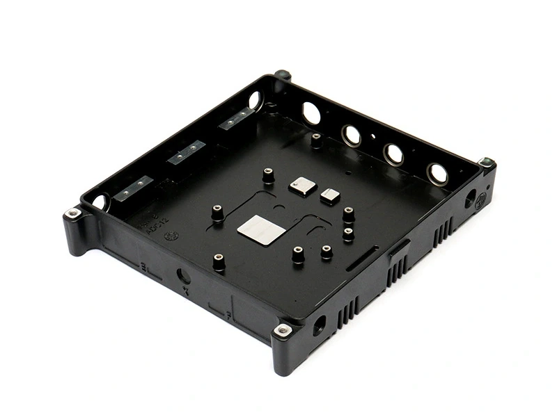
The heat-sink base is where bulk alloy performance becomes interface performance. As-cast texture, parting effects, ejector influence and casting distortion may be acceptable on external walls but unsuitable beneath a device or thermal interface material. Selected CNC machining can establish the contact plane, controlled roughness, mounting holes and datum relationship needed to create predictable contact pressure.
Machining stock must be intentional. Too little stock may leave interrupted cleanup or fail to reach the required datum plane. Excess stock adds time, changes base thickness and may open subsurface porosity. The casting drawing should state the cast target, machining allowance and protected datum pads; the finished drawing should state the thermal interface datum, flatness zone, roughness requirement, hole relationship and inspection support condition.
A thin or ribbed base can be forced flat during cutting and spring back after release. Support should not hide free-state distortion. Flatness needs temperature, support, restraint and surface condition; roughness needs its method and locations.
The handoff should include a stock map, locating scheme, tool-path boundary, opened-porosity rule and inspection record. Thermal tests must use bases approved by the same method so machining variation is not mistaken for an alloy effect.
How Porosity Changes Thermal and Sealing Performance
Porosity is not a single yes-or-no characteristic. Location, size, connectivity and function determine its effect. Distributed internal voids can alter the local path between source and fins. A pore opened by base machining can reduce contact area or collect interface material. Connected porosity near a sealed cavity can create leakage even when the external casting looks complete.
Inspection should follow the failure mode. Radiography can evaluate internal distribution in defined zones but does not prove leakage or thermal performance. Leak testing uses a specified medium, pressure, time and limit. Sectioning is local and destructive. Temperature rise evaluates the assembled path, not the cause of a poor result.
Gate, overflow and vent decisions should keep critical thermal-interface and sealing regions away from avoidable air entrapment and unstable last-to-fill conditions. Machining trials then show whether the planned stock opens unacceptable discontinuities. The drawing or control plan needs zone-based acceptance rather than a vague requirement for “no porosity,” along with a hold-and-review rule when machining exposes a pore in the thermal contact area.
Sealing or impregnation, where appropriate, addresses a defined leakage mechanism; it does not prove restored thermal contact or strength. Check compatibility with cleaning, coating, service and interface materials under change control.
How Surface Finish Affects Corrosion, Contact and Radiation
A finish changes more than appearance. Pretreatment and coating can improve corrosion protection in a defined environment, but film thickness changes fit and can insulate a thermal contact if it enters the interface. Mask boundaries should therefore separate external protection zones from the device seat, grounding lands, threaded features and other functional contacts.
Surface emissivity affects the radiative part of heat transfer, while convection, conduction, geometry, orientation and airflow can dominate the total system. A black surface is not automatically better: color alone does not establish emissivity, coating thickness, adhesion, corrosion durability or net temperature rise. The relevant evidence is a documented finish system on the actual substrate, followed by a controlled comparison of complete parts.
Cast alloy chemistry and surface condition influence finish response. The heat-sink anodizing guidance can frame that route, but buyers should still trial the specified alloy and production surface. An extruded cosmetic sample cannot approve color, film or corrosion behavior on a die casting. Porosity, silicon-rich surface features, machining and local preparation can create different results.
Approve the finish through a zone map, substrate, preparation, film range, mask transition and relevant exposure test, then repeat thermal correlation. Changes to finish source, chemistry, cure or masking reopen corrosion and thermal/interface review.
Engineering Scenario: LED Housing With Thin Fins and Machined Base
Consider an LED housing with a narrow envelope, long external fins and a machined light-engine seat. Risks concentrate at remote tips, air-escape channels, the ejected base and the contact seat. Acceptance combines fin function, base geometry and assembly temperature rise.
The team could start with A380 or ADC12 under the regional specification, retaining A360 or an A413-type direction if corrosion, pressure or fill evidence changes the weighting. An A380 lighting heat-sink example may inform questions but cannot approve this geometry or lot. Each candidate needs its certificate, data source and trial.
The first tool concept should gate along the fin corridor. Overflows and vents serve the remote edge; root transitions support flow without excess mass. Supported base regions carry ejection, and cast datums survive trimming until machining establishes the thermal-interface datum.
Trial A could hold alloy and geometry while adjusting gate or vent details. Trial B could retain the qualified tool and compare an alloy candidate justified by its certificate and data. The same stock, fixture and measurement condition separates process effects from alloy effects.
The release package correlates cavity-specific fins, base flatness/roughness, interface application, torque, heat input, ambient, sensors and stabilized rise against project limits. Material, gate/vent, fin, fixture, finish or setup changes reopen the affected comparison.
How Buyers Validate Thermal Performance Before Production
Validation should move from identity to geometry to function. The alloy certificate verifies that a lot was supplied to the specified chemistry or material requirement; it does not prove fin fill or temperature rise. Dimensional inspection verifies fin, base and mounting geometry under stated conditions; it does not prove the material value. Thermal testing verifies the assembled response under its setup; it does not identify chemistry or internal discontinuities by itself.
A simulation can rank fin, base and airflow changes when alloy value, contact resistance and boundaries are recorded. Correlate it with a physical test. Control heat, ambient, airflow, orientation, interface, mounting, stabilization and sensor position; report rise from the defined reference.
Validation Gate | Controlled Input | Evidence Produced | What It Does Not Prove | Change Trigger |
|---|---|---|---|---|
Material identity | Specification, source, lot and certificate format | Traceable chemistry/material compliance for the submitted lot | Finished-part conductivity or thermal resistance | Alloy, source, chemistry window or return-material practice |
Fin and base geometry | Drawing revision, cavity, support and measurement condition | Fill, fin profile, base flatness, roughness and mounting relationship | Assembly temperature rise | Fin, gate, ejection, machining fixture or stock change |
Porosity/sealing review | Functional zone, method, sample plan and acceptance rule | Evidence suited to internal distribution, section condition or leakage | Total thermal performance by itself | Process window, machining depth or critical-zone revision |
Finish qualification | Actual alloy, preparation, film, mask map and exposure | Corrosion, appearance and dimensional compatibility evidence | A universal emissivity or cooling benefit | Finish source, chemistry, cure, thickness or mask change |
Temperature-rise correlation | Heat, ambient, airflow, interface, mounting, sensors and stabilization | Assembly response for a traceable lot and revision | Performance under uncontrolled use conditions | Material, geometry, interface, finish, assembly or test change |
A testing overview can frame questions, but the RFQ must name the method and acceptance basis. The supplier should state the actual route, equipment identification where required, calibration, sample plan and raw-data format.
Use a pilot lot across cavities and material lots. Retain certificates, revisions, dimensions, setup records, raw readings and disposition as the change-control baseline.
What Information Belongs in a Heat-Sink Casting RFQ?
A useful RFQ defines the heat source and input, temperature limit, ambient, airflow, orientation, envelope, interface, mounting load, corrosion exposure, electrical contact, finish zones, volume and life. Mark design targets separately from contractual limits.
State the required standard and alloy or request alternatives in a common format. The bidder should identify designation, chemistry limits, condition, data source, certificate and availability. “Highest thermal conductivity” is meaningless without fin, strength, corrosion, machining and cost constraints.
RFQ Input | Thermal Decision | Casting/Machining Decision | Supplier Return | Approval or Change Control |
|---|---|---|---|---|
Heat input, source footprint, ambient, airflow and temperature limit | Defines duty and test boundary | Sets base/fin concept and critical thermal zones | Assumptions, model inputs if used and proposed test setup | Revalidate when heat source, airflow or assembly boundary changes |
Alloy standard, allowed alternatives and certificate requirement | Controls comparable property range | Controls fill, strength, corrosion, machining and supply route | Full designation, source, condition, datasheet and certificate sample | Written approval before alloy, source or chemistry-window change |
Fin CAD, flow-sensitive zones and functional damage limits | Controls effective area and base-to-fin path | Drives gate corridor, venting, overflow, ejection and trial plan | DFM notes, cavity plan, fill-risk map and trial evidence | Review any fin, gate, vent, cycle or release change |
Base datum, stock, flatness, roughness, holes and support condition | Controls contact and interface resistance | Defines casting stock, fixture, tool path and inspection | Machining plan, porosity reaction rule and measurement method | Reapprove fixture, stock, tool path or datum changes |
Finish, mask zones, corrosion exposure and interface material | Controls contact boundary and possible radiation change | Controls preparation, film build, masking and fit | Actual-alloy finish trial, thickness map and compatibility evidence | Review finish supplier, chemistry, cure, color, thickness or mask change |
Prototype, pilot and production volumes with acceptance plan | Sets correlation depth and repeatability sample | Connects tooling, yield, machining, inspection and unit cost | Stage plan, sample size, records, hold points and pricing assumptions | Release only after agreed material, geometry and temperature-rise gates |
The strongest quotation links the alloy certificate, fin-fill evidence, machined base, controlled interface and assembly temperature rise. It assigns each record and names revalidation triggers. That makes aluminium heat sink material a production decision rather than a copied property value.
FAQ
How Should Buyers Compare Published Thermal Conductivity Data for Cast Aluminum Heat Sink Alloys?
How Do Fin Height, Spacing and Draft Change the Filling Risk of a Die Cast Heat Sink?
How Should a Heat Sink Base Be Referenced for Machining and Flatness Inspection?
How Should Temperature-Rise Tests Be Correlated With Alloy and Geometry Changes?