Structural and Performance Testing with Finite Element Analysis (FEA)
Introduction
In precision manufacturing, part failure is costly, not just regarding materials and labor, but in downstream reliability, safety, and customer satisfaction. Finite Element Analysis (FEA) offers a powerful solution by predicting how a part will respond to real-world forces such as stress, strain, vibration, and thermal loads before it is ever manufactured.
At Neway, FEA is integrated into our engineering workflow to validate designs, optimize geometry, and support our clients in producing robust, high-performance components for demanding industries like aerospace, automotive, electronics, and industrial equipment.
What Is Finite Element Analysis (FEA)?
FEA is a numerical simulation technique that divides a 3D CAD model into thousands of discrete elements (a mesh). Each element is solved mathematically based on the material properties, boundary conditions, and loading scenarios applied to the part. The result is a high-fidelity prediction of how the part behaves under static, dynamic, or thermal conditions.
Common FEA Types
Analysis Type | Description | Application |
|---|---|---|
Linear Static | Calculates stress and deformation under fixed loads | General part strength validation |
Modal Analysis | Determines natural vibration frequencies and modes | Machinery, sensors, rotating components |
Thermal Analysis | Simulates heat transfer and thermal expansion | Heat sinks, enclosures, high-temp parts |
Fatigue Analysis | Predicts failure over cyclic loading | Automotive brackets, structural arms |
Buckling Analysis | Evaluates critical load for collapse | Thin-wall or axial-loaded structures |
FEA is conducted using leading software such as ANSYS, SolidWorks Simulation, and Abaqus, ensuring compliance with engineering standards and real-world behavior.
Why Use FEA in Product Development?
Benefit | Description | Value |
|---|---|---|
Design Validation | Confirms a part meets structural and thermal requirements | Reduces prototyping and redesigns |
Cost Reduction | Identifies material overuse or stress concentrations | Enables lighter, more efficient designs |
Failure Prevention | Highlights risk areas before production | Improves safety and reliability |
Faster Time to Market | Enables quicker design iterations digitally | Minimizes physical testing delays |
For example, a CNC-machined aluminum bracket analyzed via FEA revealed a 25% material overuse in non-critical regions. By optimizing wall thickness, we reduced machining time and part weight while maintaining required safety margins.
Inputs and Assumptions in FEA
FEA accuracy depends on correctly defining:
Material Properties: Elastic modulus, Poisson’s ratio, yield strength, thermal conductivity
Boundary Conditions: Constraints (fixed, roller, pinned) and contact surfaces
Load Cases: Static forces, pressure, torque, thermal loads, vibration frequency
Mesh Quality: Element density, refinement in high-stress regions
At Neway, we use verified material databases, including data for aluminum alloys, tool steels, and engineered plastics, ensuring real-world accuracy.
Design Optimization with FEA
FEA doesn’t just test a part—it actively drives better design. Our engineers use analysis results to:
Remove unnecessary mass (lightweighting)
Add fillets or ribs in high-stress zones
Redesign geometries for uniform stress distribution
Validate fastener positions, hole placement, and load paths
Evaluate deflection limits under real-use loads
These improvements often reduce material costs, shorten machining time, and extend component lifespan in the field.
FEA Applications in Manufacturing
FEA supports projects across manufacturing disciplines:
CNC Machined Parts: Stress validation for precision brackets, housings, tooling fixtures
Die Castings: Thermal and structural evaluation of thin-wall aluminum parts
Mold and Tooling: Pre-stress and thermal stress assessment for steel and H13 tool components
Consumer Products: Drop, impact, and fatigue analysis of enclosures or connectors
Automotive and Aerospace: Chassis reinforcements, engine components, structural arms
By integrating FEA early in the design process, we help clients avoid costly modifications during production or after deployment.
Integration with Prototyping and Manufacturing
FEA is part of Neway’s integrated engineering services, working hand-in-hand with:
CAD modeling and DFM: Create analysis-ready geometries
Material selection: Ensure selected alloys meet simulated loads
CNC machining: Transition seamlessly from virtual validation to physical production
Reverse engineering: Improve existing parts by validating modified designs
If necessary, we follow FEA with functional prototypes or stress-relief treatments to validate real-world performance.
Deliverables and Reporting
FEA results are delivered as a comprehensive report including:
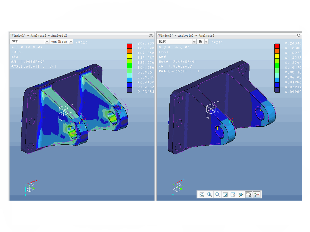
3D color-coded stress and strain plots
Safety factor distribution
Maximum deformation vectors and displacement maps
Mesh quality validation
Design recommendations for modification or approval
Reports are prepared in PDF format with optional editable simulation files for clients using compatible CAD/FEA platforms.
FAQs
What input files do you need to perform an FEA analysis?
How accurate are FEA simulations compared to physical testing?
Can FEA be used on cast, machined, and injection-molded parts?
What is the typical turnaround time for an FEA report?
Do you provide certification or validation documentation for compliance needs?