English

How does fast 3D printing integrate with CNC or casting for production?

Table of Contents
Four Hybrid Routes
Prototype First, Then Production Process
Printed Near-Net Part Plus CNC
Printed Fixtures and Tooling Aids
Printed Patterns, Molds and Cores for Casting
Requirements Transfer Matrix
Commercial and Supply Boundaries
Hybrid RFQ

Fast 3D printing integrates with CNC machining and casting in four practical ways: it validates form and interfaces before production commitment, creates near-net parts that are CNC-finished, makes fixtures or patterns for downstream processes, and supplies bridge parts while tooling is prepared. The integration is useful only when revision, datums, machining stock and test responsibility are planned together. A successful print does not prove machined-stock or casting properties, tolerances, porosity, draft or tooling behavior.

Four Hybrid Routes

Hybrid routeWhat 3D printing contributesWhat the next process contributesEvidence that does not transfer automatically
Printed fit prototype, then CNC or castingFast envelope, interface and ergonomic learningProduction-intent material, tolerance, surface and volume routeStrength, fatigue, thermal response, casting shrinkage and machining stability
Printed near-net metal plus CNCComplex material placement or internal geometryDatums, bores, threads, seals and controlled surface finishAs-printed internal quality and final residual stress without route-specific inspection
Printed jig, fixture or soft toolingFast custom workholding, gauges or handling aidsCNC/casting process creates the saleable componentFixture stiffness, wear, thermal stability and locating repeatability
Printed pattern, mold or core plus castingToolless geometry for sand or investment routeProduction-metal chemistry and cast structureFinal route capability, defect distribution and transfer to permanent die tooling

Prototype First, Then Production Process

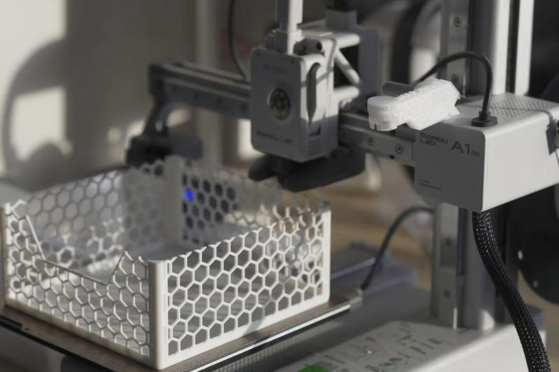
A polymer print can reveal connector interference, tool access, ergonomics and overall envelope before expensive stock or tooling is released. Mark each test result as geometry-only, assembly, fluid, thermal or structural. If the printed material and process do not reproduce the final property, do not carry the result into production approval.

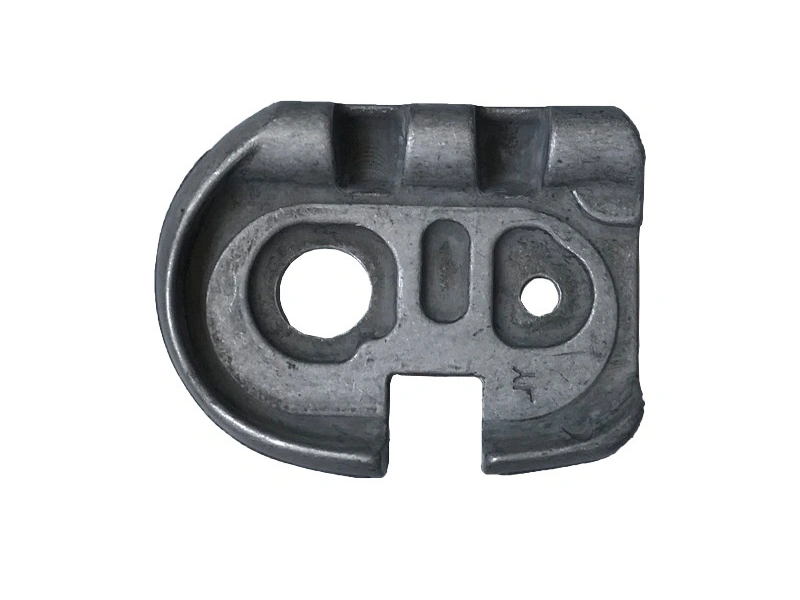
When moving to casting, revise the model for draft, parting, ejectability, wall transitions, fillets, gates, vents, shrinkage and machining allowance as applicable. When moving to full CNC, review tool access, stock shape, workholding, operation count and chip evacuation. Preserve the design-intent model and production model as separate controlled revisions.

Printed Near-Net Part Plus CNC

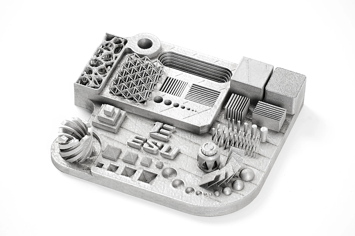
Metal additive manufacturing can create a body with internal channels or material distribution, then machining establishes interfaces that printing alone may not hold economically. Add stock at machined surfaces and create accessible datum features. Plan how the part will be held after support removal and heat treatment. Thin or flexible printed sections may move under clamping.

Sequence matters. Stress relief before machining may reduce later movement. Rough and finish machining can be separated when distortion risk warrants it. Internal features inaccessible to inspection remain an acceptance risk. The additive-plus-CNC workflow should include final-condition measurement and functional testing.

Printed Fixtures and Tooling Aids

Printed soft jaws, drill guides, assembly nests, inspection locators and handling aids can shorten setup for prototypes or low-volume work. Their value depends on stiffness, wear, creep, coolant, temperature and locating strategy. A fixture that holds one demonstration part may not remain accurate through a production batch.

Identify hard datum inserts, replaceable wear points and calibration method. Validate the fixture with a known artifact or repeated measurements. Control its file revision and print orientation. If the fixture is reprinted on another process or material, verify it again rather than assuming digital identity creates dimensional identity.

Printed Patterns, Molds and Cores for Casting

Additive manufacturing can produce sacrificial patterns, pattern equipment or directly printed sand molds and cores. This can avoid dedicated pattern tooling for prototypes and complex low-volume geometries. The casting remains governed by alloy, mold system, gating, feeding, venting, solidification, cleaning, heat treatment and inspection. Surface and dimensional behavior reflect both printed tooling and casting physics.

Use sand casting trials when the program needs production-metal learning and the sand route is relevant. A sand-cast prototype does not establish high-pressure die-casting porosity, wall capability or cycle economics. If permanent die or HPDC is the target, run a separate DFM and tooling validation before production.

Requirements Transfer Matrix

Create a matrix with every design requirement and columns for printed prototype, hybrid intermediate and production process. Form and connector location may transfer directly. Material strength, fatigue, pressure integrity, surface, heat treatment, cast defect limits and production tolerance usually need fresh evidence. Record test method, sample revision and disposition.

This prevents a common failure: changing material and process while retaining a prototype pass mark. It also protects useful learning. If a fit issue was corrected at the printed stage, trace that design revision through machining setup, casting drawing and inspection program.

Commercial and Supply Boundaries

Hybrid work creates handoffs. State who owns additive build, heat treatment, machining, casting, finishing and inspection. Identify where dimensions are measured and who dispositions nonconformance. One commercial supplier may simplify communication, but integration does not itself improve yield, cost or delivery. Records and technical ownership do.

Compare the complete route: setup, printed material, supports, heat treatment, machining stock, fixtures, casting operations, inspection, yield and logistics. The fastest prototype route may not be the lowest-cost production route. Likewise, bridge parts should have a defined stop condition when tooling becomes available.

Hybrid RFQ

Provide all revisions, final production target, annual quantity, prototype quantity, material requirements, controlled datums, load cases, interfaces, final finish and inspection. Mark which features must be production-equivalent in the printed part. For near-net machining, specify stock, datum strategy and inaccessible features. For printed casting tooling, identify casting alloy, mold process, expected quantity and later tooling route.

Ask the 3D printing, CNC machining and casting owners to agree one revision and requirements matrix. The related end-use qualification guide defines when a printed result can stand on its own. Hybrid manufacturing works when each process has a clear job and every nontransferable requirement is revalidated before release.

Copyright © 2026 Diecast Precision Works Ltd.All Rights Reserved.