Save on Manufacturing with Zero Tooling Cost in 3D Printing
 Zero-Tooling Advantage: Why 3D Printing Reduces Manufacturing Costs
As a Neway engineer involved in both additive and traditional manufacturing programs, I frequently see companies spending a disproportionate amount of their project budget on tooling long before a single functional part is created. In die casting, injection molding, or even some CNC-intensive processes, the mold or fixture becomes one of the largest cost drivers, especially when revisions are expected. This is why the shift toward digital, mold-free production has become so influential for high-mix, low-volume applications.
By adopting direct digital manufacturing through advanced 3D printing, teams can eliminate the need for tooling entirely. The workflow is straightforward: engineers prepare their CAD data, we optimize it for the specific additive process, and production begins layer by layer. Without steel tooling to fabricate, heat-treat, polish, or modify, the upfront investment drops sharply. For product developers balancing uncertain demand or still refining geometry, zero-tooling manufacturing dramatically reduces financial risk.
3D printing is particularly valuable for producing functional prototypes, bridge production parts, or customized batches in industries where short lead times are crucial. Since no molds are involved, each iteration can be printed with minimal cost impact, allowing engineers to finalize their product based on actual physical feedback rather than assumptions.
How 3D Printing Eliminates Mold-Making Expenses
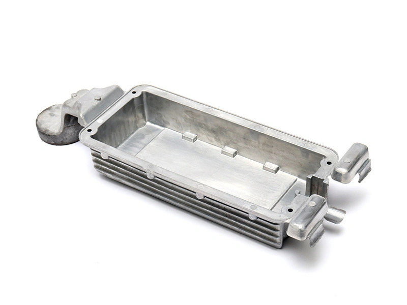
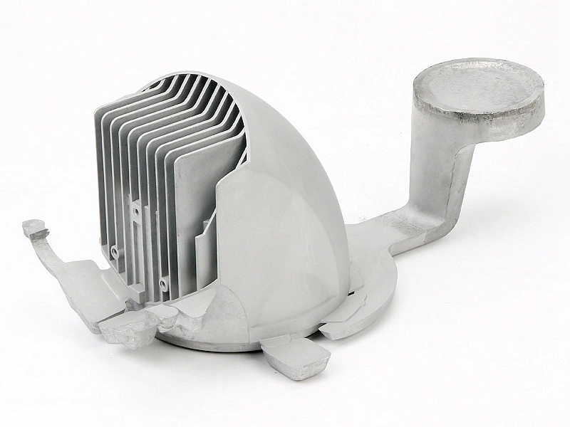
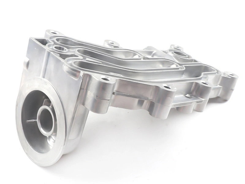
In traditional casting, dies must be machined from steel, inspected, trial-run, and adjusted—sometimes several times. Even for small components, these molds often require precision manufacturing, similar to CNC machining, which drives costs upward. A prototype mold for aluminum die casting or sand casting may cost thousands, while production molds can reach tens of thousands of dollars, depending on their complexity.
Additive manufacturing bypasses every step of this mold-making chain. Instead of investing in tooling, material is selectively added, allowing components to be built exactly as designed. For customers who previously relied on casting or urethane simulation, rapid prototyping through additive techniques offers similar part functionality while eliminating the expensive and time-consuming mold stage.
Bridge production also benefits significantly. When a customer needs a small batch of parts while waiting for mass-production casting, additive manufacturing becomes a cost-effective stopgap. There is no need to rush tooling construction, which often leads to premature design freezes and additional revision fees. Projects involving frequent modifications minimize losses because each digital iteration is directly printed without the need for remaking steel molds.
Design Freedom and Cost Reduction Through Geometry Optimization
One of the greatest financial advantages of additive manufacturing comes from its geometric freedom. In die casting or CNC machining, undercuts, thin walls, deep pockets, or internal channels often require special machining strategies or complex tooling. These raise both cost and lead time.
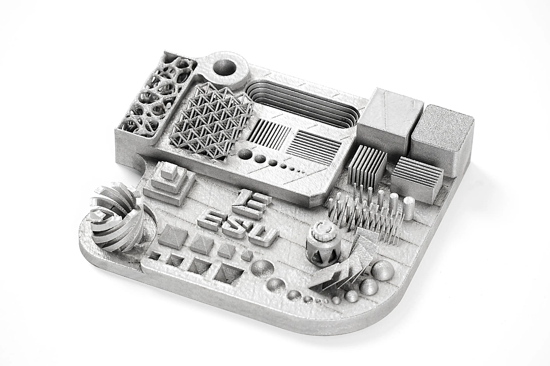
With 3D printing, the geometry of the part does not significantly influence the cost. A lattice structure, topology-optimized bracket, or highly integrated assembly can be printed without additional manufacturing complexity. This enables part consolidation—combining what was once multiple CNC or cast components into a single printed piece—reducing assembly cost and cutting down on fasteners or joining operations.
Designers also gain the freedom to create lightweight structures with organic or non-linear shapes. In industries such as aerospace or robotics, this reduces material usage, improves performance, and directly translates into manufacturing savings. When complexity becomes cost-neutral, engineering teams can optimize solely based on functionality rather than tooling limitations.
Speed, Flexibility, and Reduced Production Risk
A significant portion of manufacturing cost stems not from material or machining but from time lost in iteration cycles. With additive manufacturing, the time from CAD to physical part is compressed dramatically. Instead of waiting weeks for a mold to be produced and validated, parts can be printed in days or even hours, depending on size and material.
This speed enables faster R&D cycles and reduces the financial risk of design evolution. If customers require preliminary batches for field testing, 3D printing supports quick modifications based on real-world data. For small businesses and startups, avoiding inventory buildup is another key benefit. Since parts are printed on demand, manufacturers avoid tying capital into mold investments or large batches of stock that may become obsolete.
In high-mix environments such as consumer hardware or specialized robotics, flexibility is especially valuable. Companies can produce only the quantities needed, update designs without penalty, and dynamically adapt their supply chain.
Material Choices Affecting Zero-Tooling Applications
The effectiveness of zero-tooling manufacturing depends heavily on material selection. Additive manufacturing supports a wide range of metals and engineering plastics, making it suitable for functional prototypes and production-grade components.
For applications traditionally requiring aluminum casting alloys, teams often evaluate the mechanical trade-offs against options available through additive processes. When comparing additive-ready materials with alloys such as aluminum alloys or high-performance non-ferrous metals like copper brass alloys, the correct selection ensures that printed components achieve the necessary strength, temperature resistance, and surface finish.
Certain products that previously relied on Zamak or zinc components can transition to printed alternatives made from composite materials or metal powders. Customers also inquire about tooling materials when analyzing traditional production methods. In those cases, reviewing resources such as tool materials helps illustrate how the removal of mold requirements eliminates entire categories of cost.
Material compatibility is therefore central to evaluating additive suitability. For many industries, engineering teams find that printed materials meet or exceed performance requirements, particularly when combined with surface enhancement or hybrid machining.
Post-Processing Requirements and Cost Impacts
Although additive manufacturing eliminates tooling, some applications still require downstream treatment to meet tolerance and cosmetic standards. Depending on the final use case, 3D-printed parts may undergo one or several post-processing operations. For metal components, die castings post machining is often applied to refine features like mating faces, tight-tolerance bores, or threaded holes. For aesthetic surfaces, blasting or coating treatments comparable to post-process for die castings help achieve a uniform appearance or corrosion resistance.
The cost of these operations is generally lower compared to traditional casting, where finishing must also correct mold parting lines, draft angles, and flash. The absence of tooling in additive manufacturing reduces both variation and rework, making post-processing simpler and more predictable.
Hybrid approaches are increasingly common, combining additive manufacturing for shape creation with machining for precision surfaces. This combination maintains the cost benefits of zero-tooling while achieving dimensional accuracy suited for high-performance assemblies.
Suitable Industries for Zero-Tooling Additive Manufacturing
Many industries have already integrated additive manufacturing into their product development and production workflows. Aerospace and high-end robotics rely heavily on printed components due to the weight reduction and complex geometries that traditional manufacturing cannot easily achieve.
Automotive customers exploring low-volume custom parts can particularly benefit from solutions like automotive components, where additive manufacturing complements casting for prototype verification and the production of accessory brackets.
In consumer electronics, rapid engineering changes are common. Companies developing housings or functional hardware often use printed components during both testing and pre-production. The partnership cases involving consumer electronics hardware illustrate how zero-tooling fabrication helps validate designs before mass production.
Industries that benefit most share common characteristics: frequent design modifications, functional prototyping demands, and small-batch orders. When traditional tooling would restrict schedules or budgets, additive manufacturing becomes the more agile choice.
When 3D Printing Outperforms Traditional Casting and CNC
The decision between additive manufacturing and traditional processes requires understanding the cost structure. Casting becomes economical only when volumes justify the investment in molds. CNC machining scales well but can struggle with highly organic shapes or deep internal features.
3D printing becomes superior when: • quantities are low or medium • revisions are expected • complex geometry reduces machining efficiency • assembly consolidation provides long-term savings • time-to-market is critical
Even after considering post-processing, additive manufacturing often provides a lower total cost of ownership, particularly during early project phases. As quantities rise, customers may still move to casting or CNC, but the additive stage minimizes early financial exposure.
How to Evaluate Whether Zero-Tooling 3D Printing Fits Your Project
Companies should evaluate material, geometry, quantity, and tolerance requirements before deciding on the manufacturing route. Early engagement with engineering and design and engineering service teams helps determine feasibility.
Key evaluation factors include: • required mechanical performance • expected production volume • cost sensitivity to revisions � geometric complexity • lead-time constraints
When these align with additive manufacturing capabilities, zero-tooling solutions become the most efficient path toward functional, high-quality parts.
FAQs
How does 3D printing reduce tooling and mold-making expenses?
What production volumes benefit most from zero-tooling manufacturing?
Which materials work best for additive manufacturing without tooling?
What post-processing steps are typically required for 3D-printed parts?
How can companies evaluate whether 3D printing is more economical than casting?