Fully customizable 3D printing lets each released part differ without cutting a dedicated mold for every variant. Designers can vary dimensions, user interfaces, internal routing, identifiers, textures and selected material or finish. That freedom is real but bounded. Every variant must remain printable, cleanable, inspectable and suitable for its load and environment. The scalable asset is not merely a creative CAD file; it is a controlled model, a valid input set and an acceptance plan.
Customization creates the most value where variation changes function, fit, identification or user experience and demand is too low or uncertain to justify variant-specific tooling. It creates less value when cosmetic differences force costly manual finishing, when every configuration needs separate engineering approval, or when a stable high-volume design fits molding, casting or machining better.
Dimensions, hole patterns, cable routes, mounting features, grip profiles and enclosure envelopes can change between variants. Parametric modeling is useful when these changes follow defined relationships. A model might accept hand width, device length or connector location as input while keeping minimum wall, edge distance and assembly clearances within validated limits.
Geometry still follows the selected 3D printing process. Unsupported spans, trapped powder, inaccessible resin, fragile pins, unremovable supports, closed channels and build-envelope limits can make a mathematically valid model unsuitable for production. Each input range needs a manufacturability check.
Scanned anatomy, an existing tool, a damaged legacy component or a physical environment can supply reference geometry. The scan is not automatically the manufacturing model. Noise, holes, motion, reflective surfaces and registration error must be corrected without erasing the functional relationship. Designers also need allowance for clothing, liners, movement, fasteners, tolerance and intended contact pressure.
Fit should be demonstrated through a defined trial, not assumed from the scan. For a grip or wearable interface, specify contact zones, clearance, orientation landmarks and adjustment method. Human-derived data may be sensitive; define consent, access, retention, file naming and deletion rules before collecting it. Product suitability and any regulated use remain separate approvals.
Names, serials, logos, textures, typography, color zones and limited-edition motifs can be embedded in the model or added by finishing. Raised and recessed features need minimum size and depth compatible with orientation and surface process. Fine text can disappear under blasting, dye, primer or paint. Branding should also have documented ownership and approval.
Mass customization needs a method to prevent identity errors. The order record, generated file, build position, physical marking and inspection report must point to the same variant. A correct shape carrying the wrong name is still nonconforming. Human-readable and machine-readable identifiers should be verified after the final finish.
Material options depend on process: photopolymers for selected detail and optical goals, powder-bed polymers for support-free nesting around many geometries, extrusion thermoplastics for accessible concepts and tools, or metal additive routes for qualified metal components. Flexible polymers, rigid polymers and metals are not interchangeable simply because each can be printed.
Color, gloss, roughness and feel may come from feedstock, orientation, layer strategy, dye, sealing, tumbling, polishing, paint, coating or added soft components. A finish can alter dimensions, friction, cleanliness and durability. The post-processing route belongs in the variant specification.
Wall, rib, lattice, infill, duct and local reinforcement can be varied to address mass, stiffness, airflow or energy absorption. These parameters need a load case and analysis or test. Reducing material does not always reduce cost: thin features may print slowly, require support, distort or increase reject risk. A lattice that cannot be cleaned or inspected is not production-ready.
Topology optimization generates geometry for stated loads, constraints and objectives. It does not know every assembly, abuse or manufacturing condition unless those are included. The output must be interpreted, smoothed, designed for support/removal and validated in the printed material-process-orientation condition.
| Customization axis | Business or user value | Main manufacturing risk | Acceptance evidence |
|---|---|---|---|
| Parametric dimensions | One product architecture fits multiple devices or users | Invalid combinations, thin walls and interface collisions | Input bounds, automated checks and fit inspection |
| Scanned fit | Interface follows a person or existing object | Scan error, alignment, clearance and data privacy | Landmark verification, fit trial and data-control record |
| Identity/branding | Traceability, personalization or market differentiation | Wrong variant, illegible detail and unauthorized artwork | Order-to-part match and final-finish visual check |
| Color/texture/feel | Visual hierarchy, grip or tactile response | Lot variation, support marks and coating dimensional effect | Limit samples, roughness/color method and wear/cleaning test |
| Internal structure | Mass, airflow, stiffness or energy response | Trapped material, anisotropy, hidden defects and weak transitions | Analysis plus representative load/flow test and inspection |
| Unique batch mix | Produce many variants without variant molds | File, label, nesting and packaging mix-up | Variant manifest and serialized release reconciliation |
The fixed core carries safety, mounting, load, sealing and production rules. Variable zones contain approved dimensions, labels, texture panels or accessory interfaces. Do not expose every CAD dimension to the order configurator. Each variable should have a unit, range, increment, dependency and default. Illegal combinations need a rejection rule.
For example, increasing a grip width may require a minimum wall and move a fastener. Changing a connector may alter keep-out space and cable bend. These relationships should be encoded in the model or checked through a controlled review. A spreadsheet of dimensions without constraint logic invites valid-looking but unusable variants.
The master model has its own part number and revision. Each generated part carries a configuration or serial ID tied to input values and output-file hash or another controlled identifier. The manifest should list quantity, material, finish, orientation restriction, inspection class, marking and destination for every variant.
Generated files should not be manually renamed or edited after approval. If a correction is needed, update the master logic or issue a controlled exception. Retain enough data to reproduce an approved part, subject to customer privacy and retention requirements. "Digital inventory" is only reliable when software version, inputs and manufacturing route are known.
Testing a middle-size variant does not demonstrate minimum and maximum configurations. Select boundary combinations: thinnest wall, longest span, smallest text, highest load, most difficult orientation and worst cleaning path. Include combinations likely to interact. Simulation may screen designs, but physical evidence is needed where material/process variability or user contact governs.
Define what changes remain within the validated family and what triggers engineering review. Material, process, orientation, machine family, finish and input range may all matter. A new color may be cosmetic; a new flexible grade may change fit and load. Change categories should reflect actual risk.
Additive manufacturing reduces tooling constraints but introduces build direction, layer, support, recoater, thermal, cure, depowdering and surface constraints. Minimum feature values are process-, material-, orientation- and supplier-specific. Ask for design guidance against the actual route rather than quoting universal wall or hole numbers.
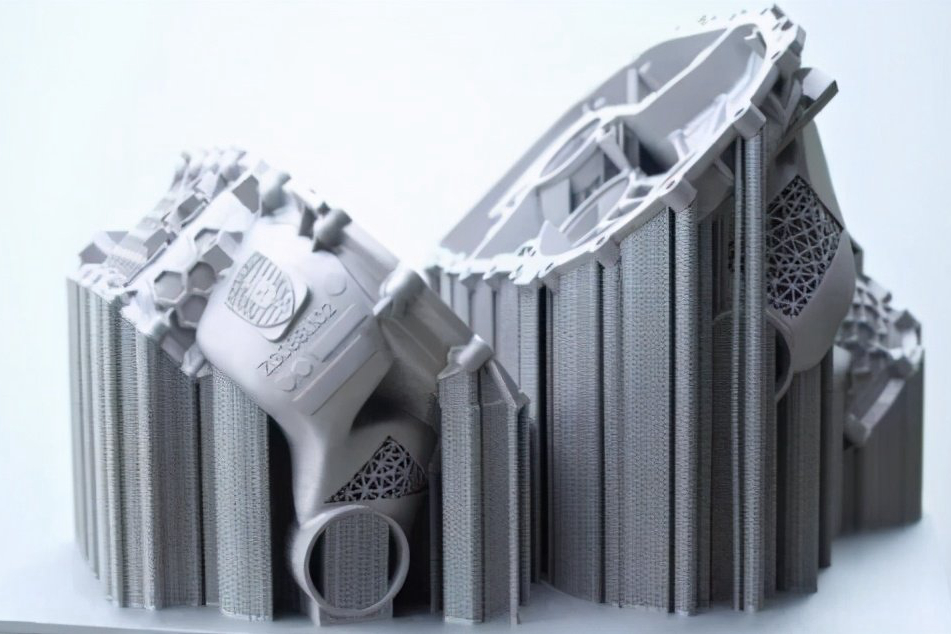
Channels need exits for powder, resin or support. Hollow bodies need drainage and cleaning verification. Fine lattices need a removal and inspection strategy. Downward faces may differ from upward faces. Metal parts can require support for heat flow and distortion control. Flexible parts may collapse during cleaning or measurement.
Split parts when it improves orientation, cleaning, service or cost, but design the joint deliberately. Alignment, fastening, adhesive gap, leak path and assembly access become new requirements. Part consolidation is useful only when it does not make inspection, repair or replacement unmanageable.
The printable material guide helps shortlist options. Final selection should state the engineering question. A transparent resin may demonstrate lighting but not long-term impact. PA12 may support a fit or duct study, but powder-bed texture and moisture condition matter. TPU can vary flexibility with process and geometry, while a metal additive alloy brings heat treatment, support, surface and internal-quality requirements.
Multi-material printing is process-specific and can add interface, purge, contamination and recyclability issues. Often a printed rigid body plus an insert, gasket, overmold or cast urethane element offers clearer control. Verify bond, mechanical retention, dimensional stack and environmental compatibility.
A customized printed part can be functional if each variant stays within a qualified design and process space. Define load direction, cycle, temperature, fluid, UV, electrical, pressure, flame, cleanliness and allowable deformation as relevant. Printed properties can vary with direction, build history, section, conditioning and post-treatment. Datasheet values are inputs, not product approval.
Fit and function may conflict. A user-specific interface can fit well but concentrate stress at a transition. A lighter lattice can meet static stiffness but fail under impact. Embedded text can create a notch. Test representative boundary variants after the final finish. For regulated or safety-related uses, establish the applicable quality and regulatory plan independently; no material name or customization claim provides that approval.
| Cost lever | Useful action | Tradeoff to review |
|---|---|---|
| Variant architecture | Keep one fixed platform and change bounded modules or surfaces | Interfaces and common core may limit visual freedom |
| Material/process | Use the least expensive available route that answers the requirement | Surface, directionality and environment may differ |
| Build orientation | Reduce supports or height where function permits | Appearance, strength and tolerance can shift |
| Finishing | Apply premium finish only to customer-facing zones | Masking and transition acceptance need control |
| Inspection | Automate invariant checks and sample lower-risk variable features | Sampling must reflect variant and failure consequence |
| Quantity planning | Group compatible variants into a controlled build | Mix-up and thermal/nesting effects need a manifest |
No dedicated forming mold does not mean zero setup cost. Every variant may add data preparation, review, labeling, inspection and packaging. The tool-free manufacturing cost discussion should be read as a comparison of complete routes.
Choose CNC machining when the custom part needs properties from stock, accessible high-precision features or a finish that would require extensive printed-part machining anyway. Use rapid prototyping to learn before locking the production route. Use urethane casting when one master can support a small set of similar soft or rigid copies and its simulated material is acceptable.
Move a stable high-demand platform toward molding or casting when accepted-part cost, capacity and consistency support tooling. Preserve customization through interchangeable inserts, machined variants, post-marking or modular assemblies. Printed prototypes do not prove draft, shrinkage, porosity, tooling, ejection or production-process properties; the model needs a fresh DFM.
master CAD/drawing revision, units, quantity, expected variant count and order mix;
fixed features, variable features, input ranges, dependencies and prohibited combinations;
part purpose, load/environment and which attributes each variant must preserve;
preferred process/material or the performance and appearance the supplier must screen;
scan source, landmarks, clearance logic, privacy, retention and approval when user data is involved;
color, texture, marking, artwork ownership, visible zones and support/contact restrictions;
final finish, inserts, machining, assembly, packaging and per-variant labeling;
inspection class, boundary validation, functional tests, reports and acceptance limits;
variant manifest format, software/configuration control, change authorization and reproduction records;
target process and requirements-transfer plan if the product may later move to casting or molding.
A supplier should return the printable design space, route assumptions, excluded combinations, sample plan, cost drivers and change rules. The design workflow should make creativity reviewable rather than rely on subjective approval at the end.
A configurator can be a CAD table, scripted model, web interface or product-lifecycle system. Whatever the tool, its output affects hardware and should be treated as a production input. Document software version, source of each parameter, calculation order, rounding, units and output naming. Lock formulas that protect wall, clearance, load and assembly requirements.
Test valid, boundary and invalid inputs. Confirm that minimum and maximum values produce the intended geometry, that linked dimensions update together, and that prohibited combinations stop rather than create a damaged file. Include unit conversion, missing data, duplicate serials, special characters and interrupted exports. Compare selected generated models to independently calculated expectations.
Software validation does not establish print capability. A model can pass logical checks and still be poorly oriented, uncleanable or outside machine limits. Add a route-specific geometry screening step before build release. When code or CAD logic changes, assess which prior configurations are affected and repeat appropriate tests.
A custom-batch supplier needs more than a machine list. Review how it receives variant data, controls revisions, prevents substitutions, creates a build manifest and maintains identity through cleaning and finishing. Loose parts can become indistinguishable after depowdering or support removal, so marking or segregated handling must survive the process.
Ask which features the supplier can inspect automatically and which require manual review. Confirm machine and material availability, permitted orientation changes, post-processing ownership, packaging segregation and reprint policy. A build containing many different parts may use capacity well but can complicate thermal behavior, identification and disposition.
The supplier should also explain change notification. Moving to another machine, material lot policy, parameter set, orientation, dye or subcontract finisher may affect validated output. Commercial flexibility should not bypass the agreed technical envelope.
Traditional sampling assumes repeated units. Mass customization may produce few or no identical pieces, so the plan separates invariant process characteristics from variant-specific characteristics. Material identity, build records, cure/heat treatment and equipment controls can be monitored by build. Unique fit dimensions, markings and order identity may need unit-level verification.
Use risk to set inspection. A decorative name can be checked visually on every part. A bounded size family may use automated model checks plus physical boundary validation and periodic dimensional verification. A safety- or load-related variable may require calculation or test per configuration class. State how nonconformance affects other variants from the same build.
Traceability closes the loop. The purchase input, generated file, build position, process record, finishing batch, inspection and shipped label should agree. If a field issue occurs, this chain identifies whether the cause came from input data, generation logic, manufacture, finishing or use.
A customization program should state when direct printing will be reconsidered. Triggers may include stable demand, repeated configurations, queue constraints, excessive finishing labor, unacceptable variation or a material requirement better served by another process. Review accepted-part cost and capacity at planned intervals rather than waiting for shortages.
Transfer requires more than sending the nominal CAD model. Provide variant frequency, boundary configurations, interface drawings, acceptance samples, failure history, material/finish requirements and tests. The target molding, casting or machining team must redesign features for its own tooling and process physics. Printed validation remains useful for geometry and user feedback, but production material, tolerance and defect behavior need fresh evidence.
Customization can also remain hybrid. Common load-bearing bodies may move to a higher-volume route while printed adapters, identity panels or user interfaces preserve variation. Define revision ownership and tolerance stacks across both supply streams. An intentional exit plan protects the digital work already completed and prevents customization from becoming permanent process lock-in.
Customizable 3D printing is strongest when digital variation has a clear user or business purpose and every output remains inside a validated manufacturing envelope. Use a constrained master model, a traceable variant manifest and boundary tests. Match material, orientation, finish and inspection to the function. That still leaves substantial creative freedom, but it turns customization into a repeatable product system instead of a collection of uncontrolled one-off files.