How are vane geometries optimized for different pump designs?
How Are Vane Geometries Optimized for Different Pump Designs?
Role of Vane Geometry in Pump Performance
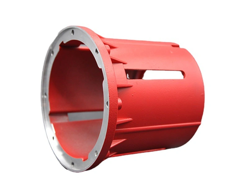
Vane geometry is central to pump efficiency, pressure stability, and flow behavior. In centrifugal, axial, and mixed-flow pumps, vanes guide fluid motion, influence head pressure, and control turbulence. At Neway Die Casting, vane optimization is integrated into tooling and design workflows to match performance requirements across HVAC, marine, chemical, and automotive pump systems.
Key Design Parameters for Vane Optimization
Parameter | Typical Range / Value | Functional Impact |
|---|---|---|
Vane Angle (Entry) | 15°–35° | Controls flow entry velocity and cavitation risk |
Vane Angle (Exit) | 20°–60° | Affects head generation and efficiency |
Number of Vanes | 5–8 (standard) | Balances flow uniformity and pulsation |
Vane Thickness | 2–6 mm (depends on material) | Influences structural rigidity and flow resistance |
Vane Curvature | Variable-radius, logarithmic | Reduces turbulence, improves flow path stability |
Tip Clearance | ≤0.2 mm | Critical for minimizing recirculation losses |
Optimization Strategies by Pump Type
Centrifugal Pumps
Backward-curved vanes minimize radial thrust and increase efficiency.
Closed impeller design is used for high-pressure, clean fluid systems.
Vanes shaped with 3D curvature optimize pressure rise and reduce blade loading.
Axial Flow Pumps
Hydrofoil-shaped vanes ensure low-resistance, high-volume flow.
Larger entry angles reduce entry shock and streamline performance.
Suitable for cooling systems and low-head, high-flow HVAC applications.
Mixed-Flow Pumps
Combination of radial and axial blade design provides moderate head and high flow.
Often used in automotive coolant or circulation systems.
Vane optimization focuses on balancing efficiency and NPSH requirements.
Computational and Manufacturing Considerations
CFD Simulation: Fluid dynamics modeling is used during design to assess flow velocity, pressure distribution, and cavitation zones across the impeller.
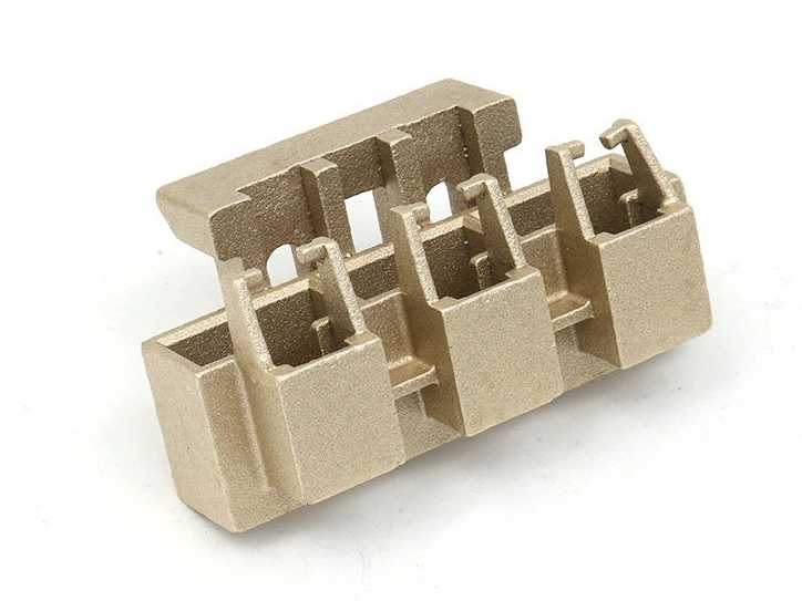
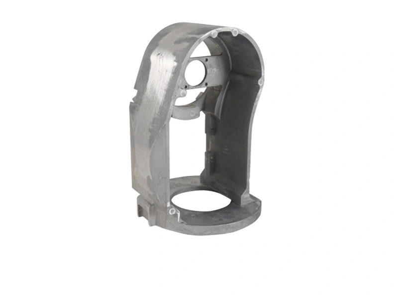
Castability: Die design must accommodate vane undercuts, thickness transitions, and flow channels. Alloys like C87500 silicon bronze and C95800 aluminum bronze allow stable casting of complex vanes.
Post-Machining: CNC finishing is applied to trim vane edges, maintain tip clearance, and correct geometric deviations after casting.
Validation and Testing Methods
Vane geometry is verified via 3D scanning and CMM inspection.
Hydraulic testing confirms pressure head, flow rate, and efficiency.
Dynamic balancing ensures smooth rotation at operational speeds.
Customer-Oriented Pump Impeller Services
Neway Die Casting supports high-performance vane design and production through:
Copper and Bronze Die Casting: Stable and corrosion-resistant casting of precision vanes
Tool and Die Creation: Mold design to support vane draft, undercut, and cooling flow
Engineering Support: CFD-aided optimization for performance-critical impellers