What Is Zinc-Zamak Die Casting? Step By Step
Introduction: Why Is Zinc Alloy Die Casting So Popular?
In the field of precision metal component manufacturing, zinc alloy die casting holds a unique and irreplaceable position due to its distinct advantages. As a die casting engineer at Newway, I have seen many customers successfully improve both product quality and cost efficiency by choosing zinc alloy die casting. Whether for visually refined consumer products or dimensionally precise industrial parts, zinc alloy die casting consistently delivers satisfying solutions. This article will guide you through the technical details of this process, systematically breaking down the complete manufacturing workflow from raw material to finished part.
What Is Zinc Alloy (Zamak) Die Casting?
Definition of Zinc Alloy Die Casting
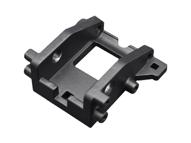
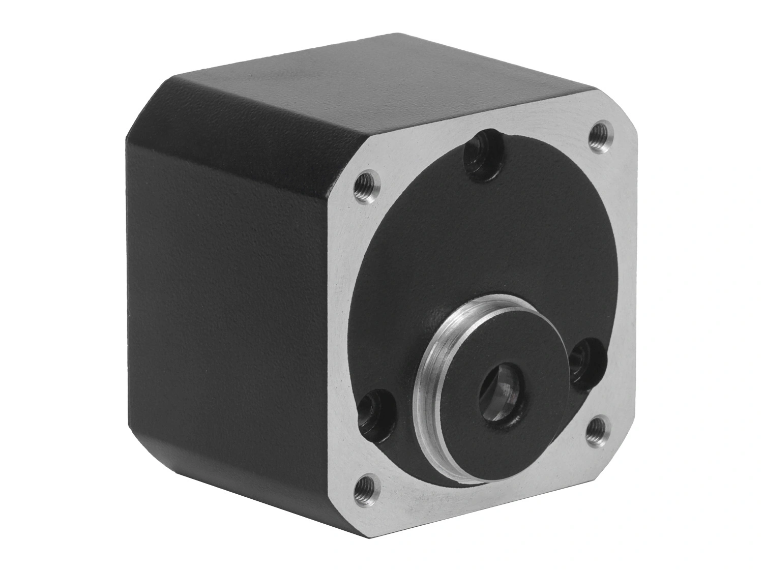
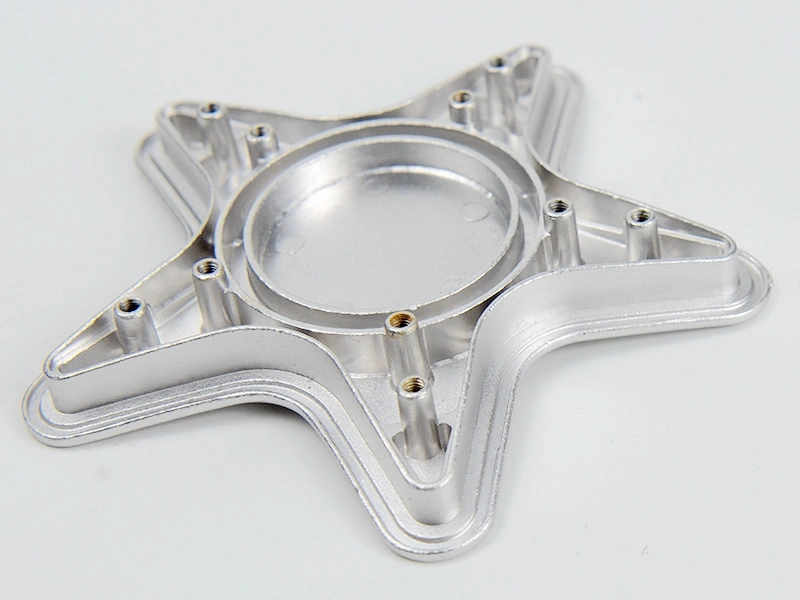
Zinc alloy die casting is a manufacturing process in which molten zinc alloy is injected into a precision mold cavity under high pressure and rapidly cooled to form the desired part geometry. This process is particularly suitable for small- to medium-sized parts with complex structures and tight dimensional requirements. Its core material, Zamak, is an alloy of Zinc, Aluminium, Magnesium, and Copper—the name “Zamak” itself is derived from the initials of these elements in German.
Core Properties of Zamak Alloys
Zamak alloys offer a combination of outstanding material characteristics that make them ideal for die casting. First, they provide excellent casting fluidity, enabling complete filling of fine mold details and resulting in smooth surfaces and sharp contours. Second, zinc alloys exhibit impressive mechanical strength, with tensile strengths of up to approximately 358 MPa and Brinell hardnesses of around 82 HB—outperforming many engineering plastics and some aluminum alloys. In addition, zinc alloys exhibit superior surface finishing capabilities, making them highly compatible with various electroplating and coating processes.
Zinc Alloy Die Casting vs. Other Die Casting Processes
Compared with aluminum die casting, zinc alloys have a lower melting temperature (approximately 380–420°C), which reduces energy consumption and minimizes thermal shock to the mold, thereby extending mold life. Relative to magnesium die casting, zinc alloy die casting offers advantages in cost control and process maturity. In thin-wall applications, zinc alloys excel, reliably producing parts with wall thicknesses as low as 0.5 mm—an important advantage in many design scenarios.
Step-by-Step Process of Zinc Alloy Die Casting
Step 1: Mold Design and Manufacturing
A precision mold is the foundation of zinc alloy die casting, as its quality directly determines the accuracy and consistency of the final products. Our die mold manufacturing team uses advanced design software and machining equipment to ensure every mold meets stringent technical requirements. Mold design must comprehensively consider factors such as alloy shrinkage, draft angles, cooling channel layout, and venting, while ensuring sufficient strength and wear resistance to support high-volume production.
Step 2: Alloy Melting and Preparation
Melting of Zamak alloy must be carried out under tightly controlled temperature conditions, typically maintained around 420°C. We use automated melting systems to ensure uniform composition and stable alloy quality. During melting, special attention is paid to preventing contamination by iron, as even trace amounts of iron can adversely affect fluidity and mechanical properties.
Step 3: Mold Clamping and Injection
Once the mold is prepared and the alloy reaches an optimal molten state, the die casting machine applies a clamping force of about 50–100 MPa to lock the mold. The shot piston then injects the molten zinc alloy into the mold cavity at a speed of approximately 15–45 m/s. Timing at this stage is critical: the entire injection usually completes within 0.01–0.2 seconds to ensure the alloy fully fills every corner of the mold before solidification begins.
Step 4: Cooling and Solidification
After the injection, the casting begins to cool and solidify inside the mold. Thanks to the rapid solidification characteristics of zinc alloys, this step is relatively short—typically only a few seconds. Cooling water channels within the mold precisely control temperature, ensuring uniform cooling and minimizing defects such as shrinkage, porosity, or deformation caused by excessive temperature gradients.
Step 5: Mold Opening and Ejection
When the casting has sufficiently solidified, the die casting machine automatically opens the mold. A carefully engineered ejection system then activates, using ejector pins to smoothly dislodge the casting from the cavity. This step requires precise timing and a controlled ejection force to ensure easy demolding without deforming the part or damaging its surface.
Step 6: Trimming and Gate Removal
After ejection, the casting still carries gates, runners, overflow features, and other excess material, which must be removed using dedicated trimming dies. This operation is typically integrated into an automated production line to guarantee consistent dimensions. The trimmed runners and scrap are immediately recycled, highlighting the environmentally friendly, 100% recyclable nature of zinc alloys.
Post-Casting Finishing and Surface Treatments
Essential Cleaning Processes
After basic trimming, further surface refinement is required. We use mechanical deburring techniques, employing precision vibratory finishing equipment to remove fine burrs along edges. For parts with specific surface appearance requirements, sandblasting may be used to achieve a uniform matte finish or customized textures. These treatments not only enhance appearance but also provide a solid foundation for subsequent coating processes.
Precision Secondary Machining
For areas that demand higher dimensional accuracy, we offer professional post-machining services for die castings. Utilizing high-precision CNC machining equipment, we can precisely fine-tune critical dimensions to meet stringent assembly tolerances. This combined approach leverages the high efficiency of die casting and the high precision of machining to deliver the most cost-effective solution.
Surface Treatments to Enhance Appearance and Performance
Zinc alloys are highly compatible with a wide range of surface finishing processes. Depending on customer requirements, we can provide electroplating, liquid painting, or powder coating. Electroplating can give parts a premium metallic appearance while significantly improving their corrosion resistance. Powder coating offers rich color options and durable protective layers, making it ideal for both functional and decorative purposes.
Key Material Selection: Understanding the Zamak Family
Zamak 3: The General-Purpose Choice
Zamak 3 is the most widely used zinc alloy for die casting, known for its excellent fluidity and dimensional stability. It is particularly suitable for complex, thin-walled components and performs well across a broad spectrum of industrial and consumer applications. Its balanced properties and cost-effectiveness make it the first choice for many projects.
Zamak 5: Higher Strength and Hardness
When parts must withstand greater loads or higher wear, Zamak 5 is an ideal option. With about 1% copper content, it offers roughly 10% higher strength and hardness than Zamak 3, while maintaining good castability. This alloy is commonly used for lock components, hardware, and tool parts that require enhanced mechanical performance.
Other Special Zinc Alloys
In addition to the standard Zamak series, we offer a range of special zinc alloys specifically designed to meet the unique requirements of various applications. For example, ZA-8 and similar alloys provide higher working temperature capabilities while retaining good casting properties, and certain low-copper formulations are specifically designed to improve electroplating performance for decorative or functional coatings.
Key Advantages of Zinc Alloy Die Casting
Zinc alloy die casting stands out among many manufacturing methods due to its multiple strengths. It can achieve very high dimensional accuracy, with tolerances typically controlled within ±0.05 mm, satisfying most precision assembly requirements. The process supports thin-wall designs, with minimum wall thickness as low as 0.5 mm, providing greater design freedom. From a productivity perspective, zinc alloy die casting offers short cycle times, making it ideal for high-volume production. Furthermore, the excellent as-cast surface quality often allows parts to be used directly or with minimal finishing before coating or assembly.
Wide-Ranging Applications of Zinc Alloy Die Castings
Automotive Industry
In automotive manufacturing, zinc alloy die castings are widely used for interior components, door lock systems, sensor housings, and other parts. These components require precise dimensions, attractive appearance, and sufficient mechanical strength—requirements that zinc alloy die casting fulfills exceptionally well.
Consumer Electronics and Home Appliances
Consumer electronics demand both high aesthetics and tight tolerances. From laptop hinges to smart home device housings, zinc alloy die casting provides both structural integrity and premium surface quality. Its good electromagnetic shielding performance also makes it advantageous for electronic enclosures.
Hardware and Locks
The hardware and lock industries are traditional strongholds for zinc alloy die casting. Door handles, lock cylinders, and related components can be produced with intricate internal structures and refined external shapes while maintaining durability and reliability.
Fashion and Consumer Products
In the fashion and branded consumer goods industries, we have produced exquisite belt buckles and elegant perfume bottle caps for well-known brands. These products demonstrate the exceptional compatibility of zinc alloy die casting with surface finishing, allowing for finishes ranging from mirror-like chrome to vintage-style patinas.
Choose Newway for Professional Zinc Alloy Die Casting Solutions
At Newway, we have accumulated more than a decade of expertise in zinc alloy die casting. Beyond advanced production equipment and comprehensive quality inspection systems, our greatest strength lies in our experienced engineering team, which offers full technical support from design optimization through to mass production. Our post-processing capabilities ensure every part meets the highest standards, while our one-stop service model allows customers to focus on their core business. For example, the complete zinc alloy die casting and finishing solution we provided for Philips electric shaver housings fully demonstrates our integrated capabilities in this field.
Conclusion: Choosing the Ideal Manufacturing Process for Your Project
As a proven and reliable manufacturing technology, zinc alloy die casting strikes an excellent balance among precision, efficiency, and cost. Whether for high-volume industrial parts or design-driven consumer products, it delivers robust and competitive solutions. We encourage product developers to consider the characteristics of zinc alloy die casting at the earliest stages of their projects and to collaborate with professional engineering teams to fully leverage its advantages and create more competitive products.
Frequently Asked Questions (FAQ)
What are the main differences between Zamak 3 and Zamak 5? How to choose?
What is the minimum wall thickness achievable for zinc alloy die castings?
Is zinc alloy die casting suitable for outdoor applications? How about its corrosion resistance?
What is the typical production lead time for zinc alloy die castings?
Can Newway support low-volume trial production of zinc alloy die castings?