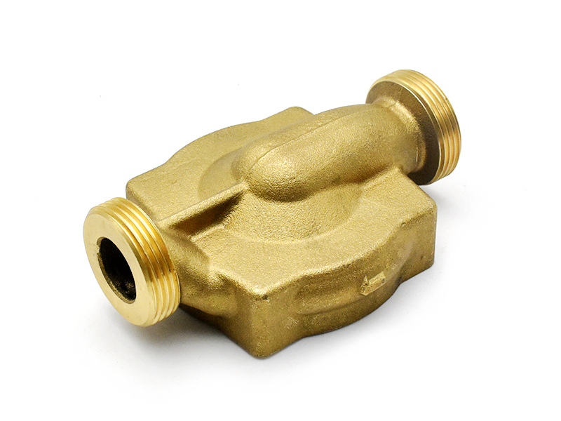
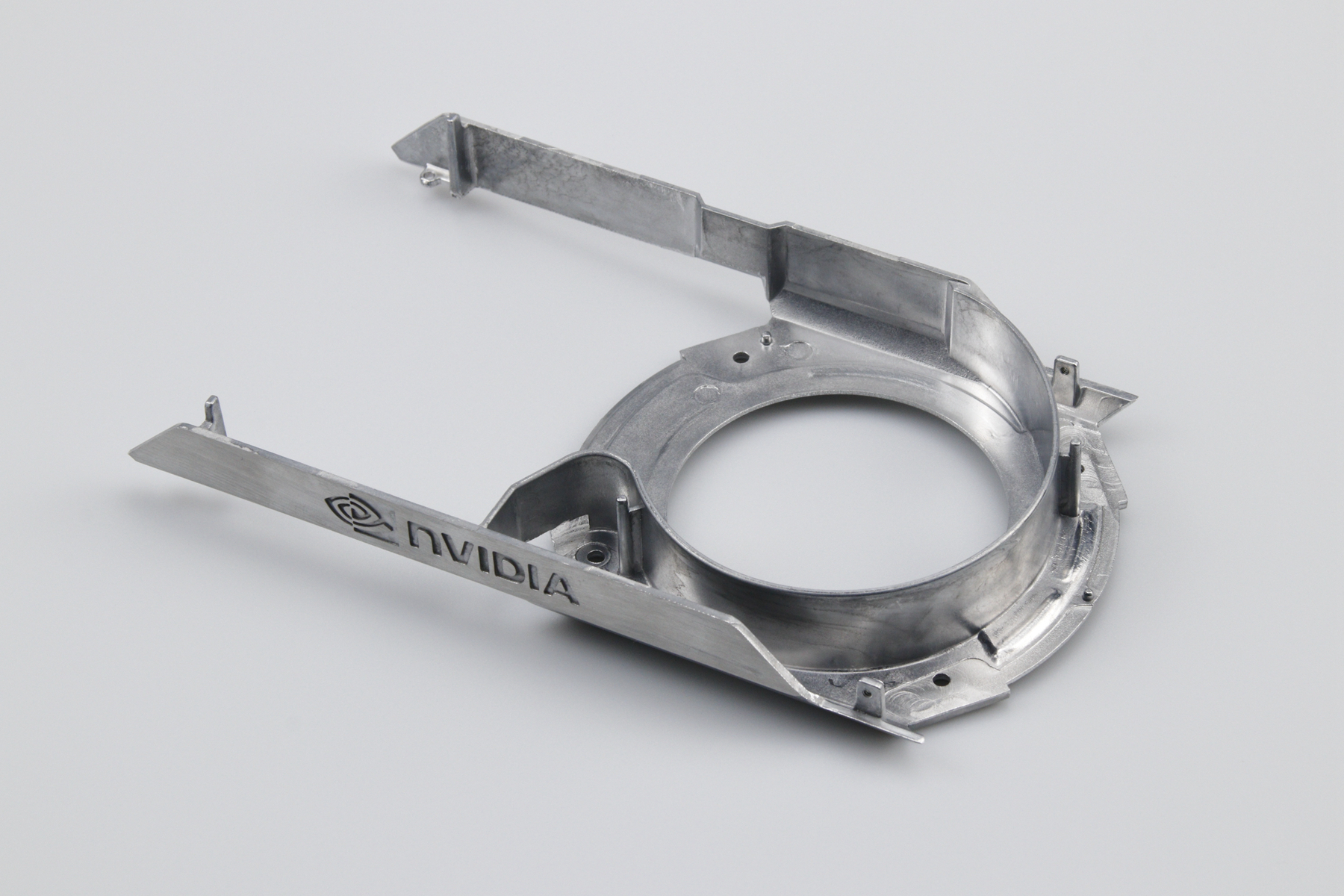
Choose a copper-based die-casting route when electrical or thermal resistance, wear behavior, pressure service, corrosion response, or compact metal integration creates enough product value to justify the alloy cost and demanding tool conditions. First verify two separate questions: does a named copper alloy meet the finished-part duty, and can that exact alloy and geometry be made by the proposed casting process? A useful copper grade is not automatically suitable for high-pressure die casting.
“Copper die casting” covers materially different brasses, bronzes, copper-nickel alloys, precipitation-hardenable copper alloys, and special casting compositions. Some grades are commonly associated with machining, forging, sand casting, permanent-mold casting, centrifugal casting, or another route. The supplier must identify the process, material condition, tooling, section capability, and validation evidence rather than treating every copper-alloy page as a process approval.
State the product requirement in system terms. For an electrical terminal, define current, duty cycle, allowable temperature rise, contact resistance, joint force, plating, fault condition, and environment. For a heat spreader, define source power, heat path, interface area, coolant or airflow, maximum component temperature, pressure drop, and thermal cycles. For a bearing or valve component, define load, speed, mate, lubricant or fluid, wear, leakage, corrosion, and life.
Separate the properties that compete. Alloying that improves strength, hardness, casting behavior, or corrosion resistance can reduce conductivity. A high-conductivity grade may need a heat treatment or wrought condition that the proposed casting route does not reproduce. A marine alloy may resist one seawater mechanism but be unnecessary or unsuitable for a high-current contact. Select the minimum property combination that satisfies the product rather than asking for “maximum copper performance.”
Use published data only when grade, condition, test method, section, and temperature are relevant. Validate the finished casting and assembly. Contact preparation, porosity, section change, machining, coating, fastener pressure, and surface oxidation can dominate actual electrical or thermal performance.
A designation such as brass, aluminum bronze, copper-nickel, or chromium copper describes a material family, not one casting method. Composition, liquidus range, oxidation behavior, die interaction, shrinkage, hot tearing, pressure tightness, and required condition affect process feasibility. The RFQ should ask the supplier to name the exact alloy, applicable designation, casting route, machine concept, and delivered condition.
C18200, for example, is often considered where conductivity and strength matter, but a buyer must confirm whether the required properties depend on a specific thermomechanical or heat-treated condition and whether the proposed casting process can supply it. Likewise, Brass 360 is known as a machining-oriented grade; its presence in a catalog is not enough to establish pressure-die-casting suitability.
When a grade is better established in gravity, permanent-mold, sand, investment, or centrifugal casting, compare that route honestly. The best manufacturing choice may still be a cast copper-alloy part, but not a high-pressure die casting. Route clarity prevents property substitutions, invalid prototype comparisons, and tools built around an alloy that cannot meet the intended condition.
Copper-based components can earn their cost in terminals, contact carriers, switchgear parts, grounding hardware, electrode components, and high-current interfaces where electrical loss or temperature rise controls system size and reliability. The design must consider the complete path: bulk alloy, length and cross-section, contact surfaces, joints, plating, oxide, fastener force, thermal environment, and aging.
A high conductivity percentage does not guarantee low assembly resistance. A rough, contaminated, oxidized, under-clamped, or poorly plated interface can dominate the circuit. Mark current-entry and current-exit surfaces, required machining, plating or cleaning, joint force, and allowable resistance. Measure voltage drop or resistance on the finished assembly under the specified current and thermal condition.
Fault current, arcing, magnetic force, and heat generated at a joint may create short-duration loads that are absent from nominal operation. Define these cases and verify temperature rise, movement, damage, and post-event function. If only a local conductor needs copper performance, an insert, busbar, bonded element, or machined contact combined with an aluminum or polymer housing may reduce mass and tooling risk.
Copper alloys may suit heat spreaders, cooling interfaces, electrode holders, mold components, and compact fluid or thermal hardware where low thermal resistance has measurable value. Evaluate the whole path from source to sink. Wall, fins, channels, contact flatness, interface material, flow, fouling, coating, and joining can outweigh bulk conductivity.
Specify source power, heat flux, transient duty, coolant or ambient, allowable pressure drop, local boiling or erosion concerns, and temperature limits of adjacent parts. A dense copper component stores and conducts heat differently from an aluminum one, but extra mass may be unacceptable. Use thermal and fluid analysis to compare concepts, then test production-representative parts with instrumented boundary conditions.
Internal channels and pressure boundaries add casting and inspection risk. Define core or die construction, inaccessible surfaces, minimum ligament, machining intersections, cleanliness, leak medium, pressure and temperature sequence, and acceptable leakage. A room-temperature leak test does not establish thermal-cycle durability or internal cleanliness.
Brasses and bronzes are often evaluated for bushings, guides, gears, wear plates, impeller features, valve parts, and loaded hardware. Performance comes from a system of alloy condition, counterface, hardness, surface finish, lubrication, speed, pressure, contamination, alignment, temperature, and duty cycle. “Bronze is wear resistant” is not an acceptance criterion.
C95400 aluminum bronze may be screened for load, wear, and corrosion applications, but the actual casting route and condition must be confirmed. A grade used successfully as a sand casting or wrought component does not automatically provide the same integrity, fatigue, or wear behavior when pressure cast.
Define wear pair, lubricant, contact stress, velocity, cycles, temperature, permitted clearance change, debris, and failure mode. Test the real mate and surface condition. Machining direction, porosity exposure, coating, and edge geometry can determine initial wear and seizure risk.
Copper-based alloys can be useful in marine hardware, pumps, valves, fittings, heat exchangers, and seawater systems, but “copper” is not a universal marine grade. Dezincification, impingement or erosion-corrosion, crevice conditions, galvanic coupling, stress-corrosion susceptibility, sulfides, ammonia, chlorination, deposits, biofouling, flow velocity, temperature, and oxygen level affect different alloys differently.
CuNi10Fe1 or another copper-nickel grade may be considered for selected seawater duties, while a brass or aluminum bronze may fit a different mechanical and fluid condition. Confirm that the named grade is available in the proposed casting route and that its composition and condition meet the corrosion requirement.
Review the complete assembly. Contact with steel, aluminum, zinc, graphite, or other metals can drive galvanic attack depending on area ratio and electrolyte. Avoid stagnant crevices, provide drainage, control fasteners and isolation, and specify cathodic-protection compatibility where relevant. Test coupons alone may not reproduce casting skin, machined zones, joints, deposits, or flow.
Some copper-alloy surfaces can show antimicrobial activity under specified laboratory conditions. That fact does not automatically authorize a medical, food-contact, potable-water, hygienic, or public-health claim. Alloy composition, surface condition, finish, cleaning, contamination, contact time, organism, test method, and regulatory jurisdiction all matter.
A coating may isolate the copper surface and change the effect. Wear, oxidation, cleaners, and repeated handling can alter performance. If antimicrobial function is a product requirement, define the applicable claim, test protocol, regulatory path, production surface, cleaning state, and ongoing verification. Do not use an unsupported percentage or laboratory result as a sales promise.
Potable-water and food-contact applications also require review of composition, restricted elements, extraction or migration, processing, and product certification by market. A material name or supplier quality certificate is not a finished-product approval.
Copper-based alloys can impose high thermal and chemical loads on tooling and can be harder to fill than familiar zinc or aluminum systems. Geometry should avoid unreviewed thin remote walls, abrupt heavy junctions, isolated masses, sharp transitions, inaccessible vents, and tool details with poor support. Wall targets must come from alloy, route, flow length, area, machine, gate, vent, thermal control, release, and function.
Use DFM to review parting, draft, gates, runners, overflows, vents, ejectors, side actions, trim, hot spots, shrinkage, oxidation, and machining stock. Simulation can compare concepts if material and boundary inputs are credible. It cannot prove actual die life, integrity, pressure tightness, or product function.
Complexity must create value. A channel, vane, thread, gear tooth, or connector feature is useful only if it can be filled, released, trimmed, cleaned, inspected, and held through production. Otherwise, casting a simpler preform and machining or assembling the critical feature may be lower risk.
High copper-alloy casting temperatures and die interaction can accelerate thermal fatigue, erosion, checking, soldering or adhesion, distortion, and loss of detailed features. Tool material alone cannot solve the problem. Steel or insert grade, heat treatment, coating where used, preheat, thermal balance, gate velocity, section support, cooling, lubrication, cycle interruptions, maintenance, and repair all contribute.
Tool planning should identify the likely first failure features and whether they are replaceable. Define end-of-life by accepted flash, dimension, surface, gate condition, slide fit, core integrity, or functional gauge, not by a universal shot count. Quote spare inserts, maintenance, repair approval, validation after repair, ownership, and replacement responsibility.
Tool economics may favor another process at moderate demand. Compare permanent-mold, sand, investment, machining, forging, extrusion, and fabricated assemblies. A pressure-die route is justified only when integrated geometry and production demand offset tool wear, process development, and downstream inspection.
Copper alloys vary widely in machinability. Hard or abrasive phases, ductility, work hardening, interrupted cuts, porosity, and heat removal can affect tool life, burrs, smear, and surface integrity. Post-machining plans need casting stock, datum, fixture, cutting tool, coolant, contamination, burr, cleaning, and inspection requirements.
Electrical contacts may need controlled roughness, flatness, plating, oxide removal, and protection from fingerprints or packaging materials. Fluid components may require chip and media removal from channels. Wear surfaces need direction and texture consistent with the mating pair. State the final cleanliness and preservation condition rather than simply requesting machining.
Machining can expose internal discontinuities or interrupt a corrosion-resistant casting skin. Mark no-breakout, seal, pressure, current, and wear zones during casting design. Inspection after machining should answer the final functional risk, not assume raw-casting results transfer unchanged.
Dominant requirement | Route to evaluate | Evidence before selection |
|---|---|---|
Lowest practical electrical or thermal resistance in a compact path | Copper alloy or copper insert/hybrid | Named alloy condition, finished-path resistance and temperature-rise test |
Low system mass with integrated housing | Aluminum die casting | Finished mass, stiffness, thermal path and assembly comparison |
Small fine-detail hardware and decorative finish | Zinc die casting | DFM, finish samples, dimensional and load validation |
Wear, marine, or pressure duty | Specific brass, bronze, copper-nickel, steel, or polymer system | Actual fluid, load, mate, corrosion mechanism and route evidence |
Simple high-conductivity bar or contact | Wrought, forged, extruded, stamped, or machined copper | Material condition, operation count, joints and demand |
Low volume or design still changing | Machining, fabrication, or lower-tooling casting route | Revision forecast, quantity, prototype purpose and total cost |
Strength cannot be ranked by metal name. Compare the exact grade and delivered condition under the product load and temperature. Conductivity should be evaluated per finished mass, section, length, interface, and temperature rise. Cost should include material yield, tool, energy, cycle, maintenance, machining, finish, inspection, scrap, packaging, logistics, and change exposure.
A prototype result is useful only when its material state and manufacturing route match the question being asked. A machined wrought-copper prototype can confirm envelope, interfaces, current path, heat rejection, flow distribution, or assembly access. It cannot establish fill behavior, die interaction, casting porosity, cast mechanical properties, pressure integrity after machining, production surface condition, or tool maintenance. Record those limits in the test report so an encouraging functional trial is not mistaken for casting approval.
Use staged evidence. First compare system concepts with calculations and simple samples: full copper, a lower-copper alloy, a copper insert in an aluminum structure, or a conventionally machined assembly. Measure the product response that justified copper, such as voltage drop, joint temperature, thermal gradient, leakage, wear, or hydraulic loss. If a copper-based cast concept still wins, make process-representative samples from the named alloy and delivered condition. Include the intended gates, critical sections, machining stock, heat treatment, coating, and joints where they influence the result.
Separate material characterization from part validation. Chemistry and hardness help identify what was supplied. Conductivity or thermal measurements address a defined specimen or path. Radiography, computed tomography, or sectioning may reveal selected internal features. Leak, proof, wear, corrosion, thermal-cycle, and electrical-load tests address specific service risks. None of these alone proves the others. Link each acceptance criterion to a drawing zone, sample condition, method, and product failure mode.
Prototype sourcing also affects commercial decisions. Ask whether a sample came from wrought stock, a gravity-cast blank, a single-cavity development tool, or the intended production process. Identify hand finishing, impregnation, welding, selective polishing, or sorting that will not be routine. Before production approval, repeat the critical tests on cavity-identified parts made under documented settings and downstream operations. That evidence gives the buyer a defensible bridge from copper's theoretical advantage to a repeatable casting process.
Agree the trial state and evidence before tooling. Depending on function, the submission may include chemistry or material records, cavity-specific dimensions, selected internal inspection, conductivity or resistance, thermal test, pressure and leak test, wear test, corrosion exposure, coating results, assembly, cleanliness, and functional endurance. State sample condition and acceptance for each.
Use inspection that matches the mechanism. Radiography or computed tomography can support selected internal regions; sectioning can expose structure; leak and pressure tests assess a defined boundary; conductivity instruments assess a defined path or sample; chemistry verifies sampled composition. No single method proves alloy identity, internal integrity, pressure tightness, strength, conductivity, and corrosion at once. Select inspection equipment by question, geometry, resolution, and risk.
After tool or process correction, repeat affected evidence. For production, define material and cavity traceability, process controls, sampling, measurement, maintenance, containment, change notification, and reaction plans. A prototype made from wrought stock may validate geometry or a thermal concept but not cast condition or die-casting feasibility.
Provide the controlled model and drawing, exact alloy or functional property requirement, allowed material alternatives, annual and lifetime demand, lot profile, electrical or thermal duty, load and wear, temperature, pressure and fluid, corrosion environment, mating metals, service life, finish, machining, cleanliness, assembly, tests, regulated substances, market approvals, packaging, and destination.
Ask the supplier to state the proposed alloy designation, standard and condition, casting route, machine and cavity concept, expected geometry changes, outside processes, tool assumptions, trial evidence, production controls, maintenance, exceptions, and unresolved risks. The response should distinguish what is proven from what requires sampling.
Choose copper-based die casting only when the reviewed alloy and route deliver a measurable conductivity, thermal, wear, corrosion, pressure, or integration advantage that alternatives cannot provide at lower total risk. That is a narrower decision than “copper performs better,” and it is the one that can survive tooling, qualification, and repeat production.