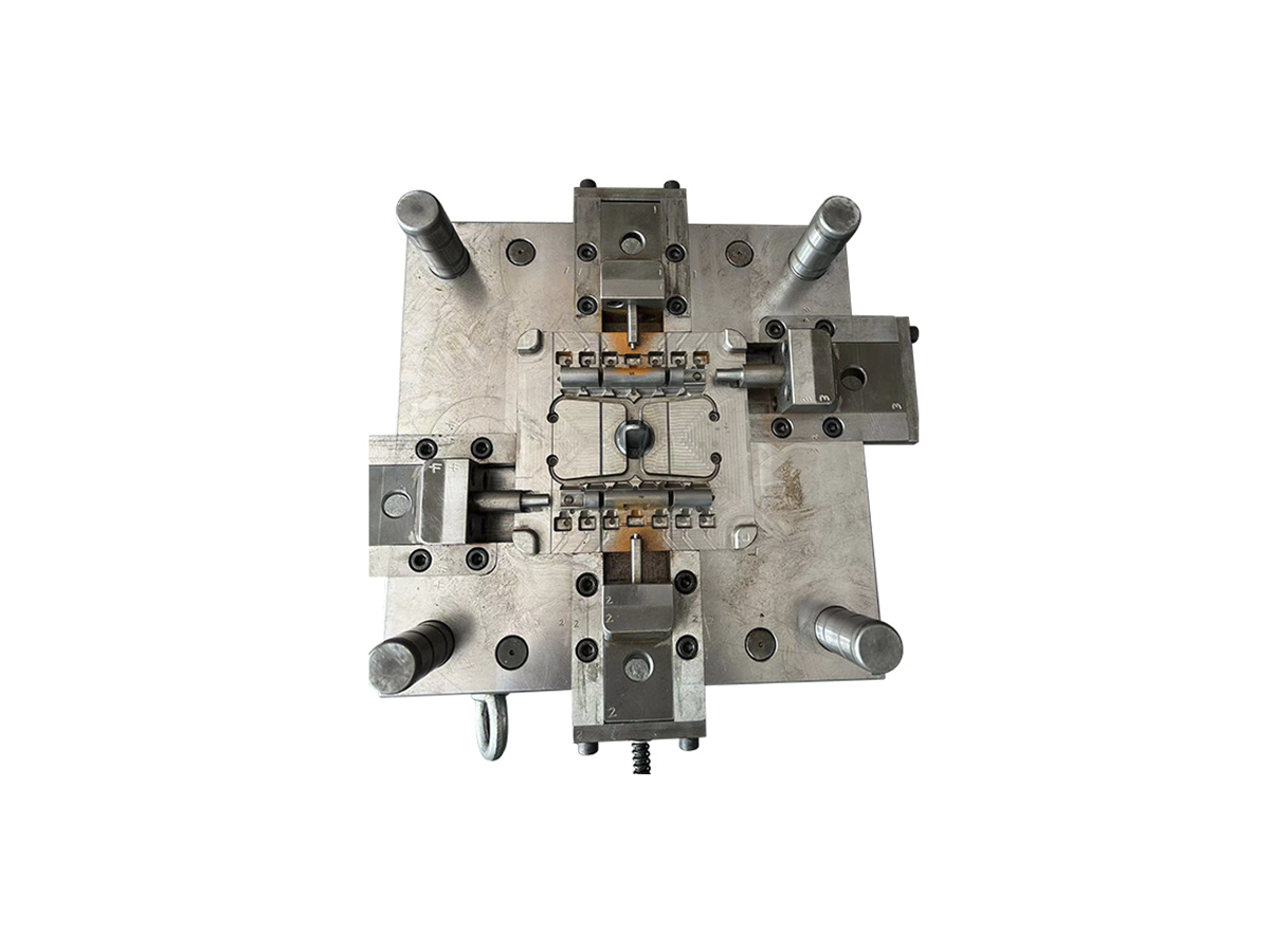
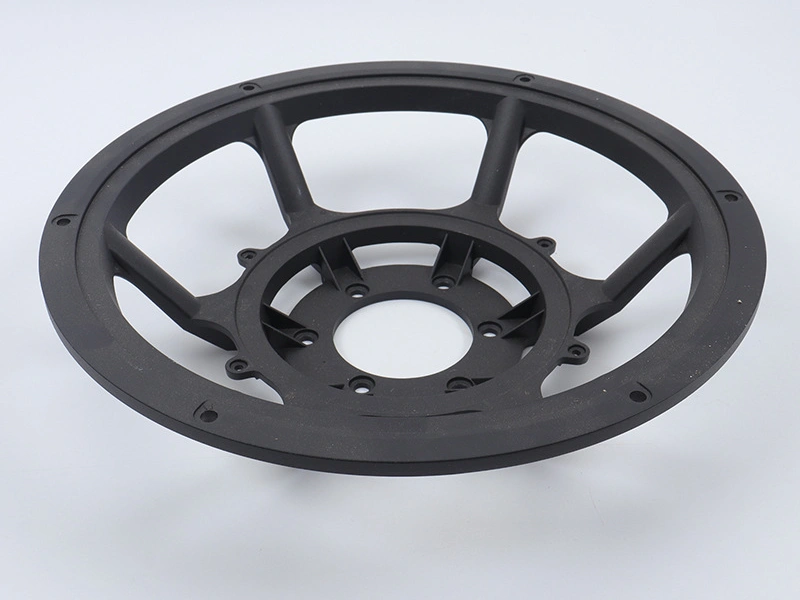
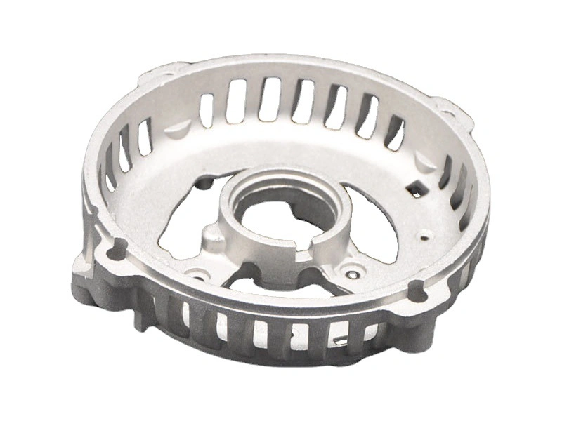
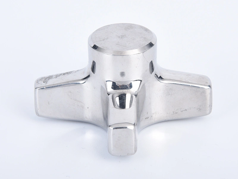
Choose tool and die materials by the failure expected in each tool region, not by production volume or a steel name alone. Start with the casting alloy, process, local metal velocity, thermal cycle, contact pressure, part geometry, surface requirement, and maintenance access. Then assign materials separately to the cavity, core, gate, slide, shutoff, ejector, support, and trim components. H13 may be a sound starting point for many hot-work regions, but it is not an automatic answer for every insert or every die.
The material designation is only one part of the decision. Steelmaking quality, stock direction, machining allowances, heat-treatment route, final hardness distribution, residual stress, surface preparation, coating, cooling, support, and repair practice can determine whether a nominally suitable grade performs well. The RFQ should therefore request a material and process plan for the tool, not a one-line promise about tool life.
Name the casting process and alloy first. High-pressure aluminum die casting, hot-chamber zinc die casting, gravity casting, squeeze casting, copper-alloy casting, plastic molding, stamping, and trimming expose tools to different combinations of temperature, pressure, impact, abrasion, chemistry, and cycle time. A material that works in a trim die may be a poor cavity steel under repeated molten-metal contact.
For the casting alloy, provide its exact designation, melt and delivery practice, expected die-contact condition, and any tendency toward soldering, erosion, oxidation, or chemical attack that the supplier has observed. Do not select tool steel from the pure metal melting point. The relevant load is the local temperature and stress history at the tool surface, including spray, cooling, interruptions, start-up, and restart.
Part geometry changes the exposure. A large flat cavity face, a deep rib, a slender core pin, a narrow gate, a sharp shutoff, and a water-cooled insert do not fail in the same way. Mark these regions on the tool concept and ask what fails first, how that feature will be inspected, and whether it can be replaced without rebuilding the whole die.
A die set is a material system. The cavity block and major inserts must survive thermal cycling and pressure. Gate inserts face concentrated velocity, erosion, and heat. Core pins combine bending, thermal gradients, adhesion, and ejection loads. Slides and shutoffs add impact, alignment, lubrication, and galling. Backing plates and holders need support and dimensional stability rather than direct molten-metal resistance.
Use replaceable inserts where the first expected failure is localized and accessible. A gate edge, narrow core, seal-off, textured cosmetic region, or hot spot may justify a different grade, treatment, or cooling strategy from the main cavity. The insert joint must still control support, heat transfer, flash, movement, and service access. An exotic insert that is poorly supported can fail sooner than a conventional one.
Trimming and piercing components belong in a separate review. Their dominant loads may be edge wear, compressive stress, chipping, impact, alignment, and debris rather than molten-metal thermal fatigue. Cold-work steel, shock-resistant steel, or carbide may fit selected trim features, but that decision should not be transferred to the casting cavity.
Heat checking develops when repeated surface heating and cooling create cyclic strain that the tool surface can no longer accommodate. Gross cracking may also start at sharp tool radii, EDM damage, tensile residual stress, deep cooling passages, poor support, local overheating, or a brittle heat-treated condition. Hardness alone does not predict either failure.
For a thermally cycled cavity, screen hot-work steel by hot strength, toughness, temper resistance, thermal-fatigue behavior, cleanliness, section capability, and heat-treatment response. Then reduce the applied strain through radii, balanced sections, credible cooling, preheat, spray control, cycle stability, and start-up procedures. A material change without correcting a severe hot spot may simply move the crack.
High-velocity metal, entrained oxides, cavitation-like pressure effects, repeated impact, and local overheating can remove material at gates, runners, overflows, and impingement zones. Loss of a gate edge changes fill behavior and may increase flash, porosity, surface defects, or trim variation before the cavity shows general wear.
Review gate geometry, velocity, impingement direction, die temperature, alloy chemistry, insert support, and replaceability before selecting a harder material. A tougher hot-work insert, a qualified surface treatment, or a selected tungsten carbide grade may be considered in a controlled wear region. Carbide grade, binder, geometry, mounting, thermal gradient, and shock determine feasibility; high hardness does not remove brittleness.
Molten alloy can adhere or react at selected tool surfaces, especially where local temperature, velocity, chemistry, roughness, oxide condition, release coverage, or ejection makes contact severe. Material transfer then damages both the tool and the casting. Polishing the symptom without correcting local filling or thermal conditions often gives only temporary relief.
Evaluate tool chemistry, surface condition, coating compatibility, lubrication, cooling, gate direction, draft, ejector layout, and cleaning practice together. Define soldering by measurable product or tool evidence: pickup location, ejection force trend, surface defect, dimension, or inspection image. This gives the team a reaction trigger instead of relying on a vague visual complaint.
Shutoffs, slides, cores, ejectors, locks, and trim edges may lose shape through compressive load, impact, misalignment, galling, bending, or abrasive wear. Increasing hardness can improve shape retention but can reduce tolerance for notches, impact, or bending. The correct balance depends on section, support, surface condition, operating temperature, and failure consequence.
Check alignment and load path before blaming material. A slender pin with poor support, a slide that closes on debris, or a trim edge with excessive clearance can damage a high-quality steel. Specify replaceable components, fit, lubrication, permissible repair, and inspection features where mechanical wear will control maintenance.
H13 hot-work tool steel is a common reference for aluminum die-casting cavities and inserts because it can offer a useful balance of hot strength, toughness, temper resistance, and thermal-fatigue performance when the steel quality and heat treatment are appropriate. That does not mean every H13 source, section, hardness, or tool detail is equivalent. Modified hot-work grades may be evaluated where cleanliness, toughness, temper resistance, or thermal-fatigue evidence supports the particular failure mode.
P20-type prehardened mold steel is attractive for machinability, availability, large blocks, and lower-thermal-duty tooling. It is commonly associated with plastic molds and may fit selected holders, prototypes, gravity tools, or mild-temperature components. It should not be substituted automatically for a hot-work cavity merely because demand is low. Even a short run can impose severe thermal shock during each cycle.
Cold-work grades such as A2 or D2 and shock-resistant grades such as S7 can suit trim, piercing, support, or selected mechanically loaded components. Their wear and impact balances differ, but published room-temperature properties do not approve direct molten-metal service. Use the intended tool temperature, edge geometry, impact, clearance, and repair method to decide.
Carbides, nickel-base alloys, copper alloys, and other specialty materials are local solutions, not prestige upgrades. They may address wear, heat transfer, hot strength, or chemical interaction in a specific insert. They also introduce machining, joining, thermal-expansion, brittleness, worker-safety, repair, availability, and cost questions. Require a stated reason for every specialty insert and a way to verify that it solves the targeted failure.
A high-conductivity copper-alloy insert can remove heat from a persistent hot spot, improve local solidification control, or reduce thermal imbalance where conventional steel and feasible cooling passages are insufficient. Beryllium copper may be considered, but the exact alloy, condition, temperature exposure, contact stress, cooling, support, casting-metal interaction, and workplace controls must be reviewed.
Do not assume that higher thermal conductivity guarantees a shorter or more stable cycle. The insert must transfer heat into a controlled cooling path. Contact resistance at the insert seat, scale in water lines, insufficient coolant flow, or an undersized heat sink can limit the benefit. Excessive local cooling can also freeze metal early, change shrinkage, increase fill defects, or create a thermal boundary that promotes cracking nearby.
Worker exposure is a separate gate. Machining, grinding, polishing, repair, and disposal of beryllium-containing materials require supplier procedures that comply with the applicable jurisdiction and material safety information. Finished solid service and airborne machining exposure are different questions. The RFQ should identify who machines and repairs the insert, what controls apply, and whether a non-beryllium alternative has been evaluated.
A steel designation without a heat-treatment plan is incomplete. Block size, stock condition, machining sequence, stress relief, austenitizing, quench method, tempering, final hardness, hardness uniformity, retained phases, decarburization, residual stress, and post-treatment machining all affect performance. Deep pockets, thin lands, cooling holes, sharp transitions, and section changes add distortion and cracking risk.
Specify the required condition by tool function and approved heat-treatment route. Final hardness should be selected within the material supplier's supported range using toughness, wear, hot strength, and geometry as constraints. A single maximum hardness is rarely the correct purchasing target. Require records and agreed verification locations, especially when a large block or multiple inserts may cool differently.
Plan machining around treatment. Leave appropriate stock, remove EDM recast or damaged layers as required, protect critical surfaces, and restore radii and finishes after hardening. If welding or major repair is permitted, define filler, preparation, thermal procedure, inspection, re-machining, and revalidation. An uncontrolled repair can create a local hardness and residual-stress condition unlike the approved die.
Nitriding, diffusion treatments, physical vapor deposition, and other surface systems may reduce adhesion, erosion, friction, or wear in selected locations. A coating is a thin interface supported by the substrate. Substrate hardness, toughness, finish, edge condition, treatment temperature, adhesion, thickness distribution, and local load determine whether the system survives.
Do not specify “hard coating” as a general die-life requirement. Name the failure to be reduced, the coated zones, excluded fits or vents, substrate preparation, treatment sequence, acceptance evidence, and stripping or recoating plan. A hard layer over a cracked, soft, rough, or poorly supported substrate will not correct the underlying problem. Review available tool coating options as candidates that still require tool-specific qualification.
Coating changes can alter dimensions, surface texture, heat transfer, release behavior, and repair options. Validate cast surface, ejection, soldering, gate condition, and critical dimensions after treatment. Track the tool state so parts made before coating, after coating, and after repair are not mixed without approval.
Material selection cannot compensate for an uncontrolled die-temperature field. Cooling channels, bubblers, fountains, inserts, contact interfaces, spray, release, coolant quality, flow, pressure, and start-up determine thermal gradients. Map predicted hot and cold zones, then confirm them during trials with suitable measurements and part evidence.
A thermal model is useful for comparing channel and insert concepts, but its inputs and contact assumptions must be credible. Trial evidence can include temperature measurements at defined times, cycle stability, fill and solidification behavior, ejection, local soldering, casting dimensions, and inspection of targeted tool surfaces. Avoid turning one surface-temperature reading into a universal die-temperature limit.
Design cooling for maintenance. Identify inaccessible passages, seals, connectors, corrosion or scale risk, cleaning method, leak test, and safe replacement. If a small insert depends on close thermal contact, define seat finish, fit, assembly, and verification after service. Degraded cooling can look like a material failure until the circuit is inspected.
Tool region or observed risk | Material direction to screen | Evidence before approval |
|---|---|---|
Main aluminum die-casting cavity with repeated thermal cycling | Qualified hot-work tool steel such as H13 or a justified modified grade | Steel source and condition, heat-treatment plan, geometry review, thermal balance, trial inspection |
Localized gate washout or impingement | Replaceable hot-work insert, qualified coating, or selected carbide system | Gate analysis, support and mounting, wear trend, casting effect, replacement method |
Persistent hot spot inaccessible to normal cooling | High-conductivity insert or redesigned steel insert and cooling path | Thermal model, insert condition, contact and coolant design, cycle and part validation, safety review |
Slide, shutoff, core, or ejector damage | Hot-work, shock-resistant, wear-resistant, or locally treated component | Load and alignment, temperature, lubrication, fit, toughness, inspection and replacement trigger |
Trim or piercing edge wear | Cold-work or shock-resistant steel; carbide where mounting and impact permit | Part condition, clearance, edge load, chipping risk, sharpening and alignment plan |
Holder or backing structure without direct metal contact | Stable support steel chosen for stiffness, machinability, availability, and repair | Load path, deflection, interface fit, temperature and maintenance access |
The table is a screening tool, not a material approval. Final selection depends on exact alloy, die size, section, process settings, tool construction, supplier data, and observed failure. Ask tool and die engineering to explain why each material appears on the bill of materials and what alternative is available if sourcing or validation fails.
Before steel release, review the controlled part model, casting alloy, machine concept, cavity count, parting, gates, runners, overflows, vents, vacuum where used, slides, cores, ejectors, cooling, trim, critical dimensions, cosmetic zones, and service plan. A formal engineering review should record open assumptions rather than hiding them behind a tool-life estimate.
At trial, identify material heat or lot where practical, insert and cavity identity, heat-treatment records, initial dimensions, surface state, coating state, and cooling condition. Inspect the actual high-risk regions after the planned trial sequence. Product dimensions alone may not reveal early heat checking, gate recession, soldering, core bending, slide pickup, or cooling blockage.
Use each inspection method for a defined question. Hardness measurements address local condition at the tested point. Metallography can investigate structure. Dimensional and surface checks track wear or movement. Dye penetrant or other NDE may support selected crack questions. Cooling flow and leak tests assess circuits. Casting inspection and functional tests show how tool condition affects the product. Available inspection equipment should be selected by resolution, access, material, and failure mechanism.
A universal shot count is not a reliable purchasing specification. The first unacceptable condition may be a cracked core, worn gate, flash at a shutoff, changed texture, distorted slide, blocked cooling line, dimensional drift, soldering, or a repair that no longer meets the approved part. Different cavities and replaceable inserts can reach those conditions at different times.
Define end-of-life and maintenance triggers by observable features. Examples include gate dimension, flash limit, cavity surface boundary, critical casting dimension, ejector or slide fit, cooling performance, crack indication, repair depth, or functional gauge result. Record parts since maintenance, failures by location, repair history, and changes to process or alloy. Trends support decisions better than an unqualified lifetime promise.
Commercial terms should distinguish initial die set, replaceable inserts, spare components, preventive maintenance, normal wear, crash damage, engineering changes, storage, ownership, repair approval, and validation after repair. A lower initial tool price can be expensive if the first-wear features are integral and inaccessible.
Provide the controlled drawing and model, casting process and exact alloy, annual and lifetime demand, lot pattern, machine constraints, cavity target, critical and cosmetic features, pressure or leak zones, insert restrictions, joining and trim, expected change exposure, maintenance location, and required trial evidence. State whether demand is a forecast or a committed program.
Ask the supplier for a region-by-region material list, material standards and approved alternatives, steel source and condition, heat-treatment route, target condition and verification, coatings, cooling concept, replaceable details, tool drawing approval, trial plan, inspection, maintenance, repair, spares, ownership, storage, and change notification. Request exceptions explicitly. Do not allow “H13 tool” to stand in for this information.
The right tool and die material is the material system that controls the expected failure at acceptable total cost while remaining manufacturable, inspectable, maintainable, and replaceable. That answer may use hot-work steel for the cavity, a different insert at the gate, a high-conductivity insert at one hot spot, a shock-resistant trim component, and an economical support steel elsewhere. The choice is defensible when every region has a reason, a verification method, and a reaction plan.