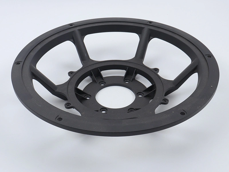
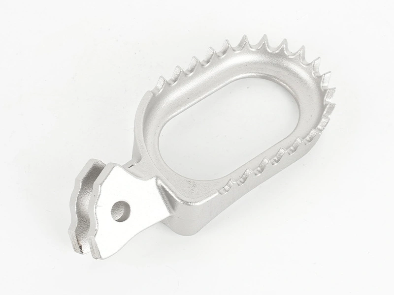
CNC Machining vs Casting: Choosing the Best Manufacturing Method
CNC machining is usually the better starting point when quantities are limited, the design is still changing, or most important features require direct access from cutting tools. Casting is usually better when a stable design can use near-net geometry, integrated ribs or bosses, and repeated production to justify a mold. Many commercial parts should use both: cast the economical shape, then machine only datums, bores, sealing faces and threads that need tighter control.
The decision cannot be made from annual quantity alone. Compare two manufacturable designs, not one drawing priced by two processes without adaptation. The useful question is which route produces an acceptable component at the lowest total delivered cost while controlling technical and supply risk. Geometry, alloy form, defect sensitivity, inspection, design maturity and forecast stability determine that answer.
Start with functional equivalence
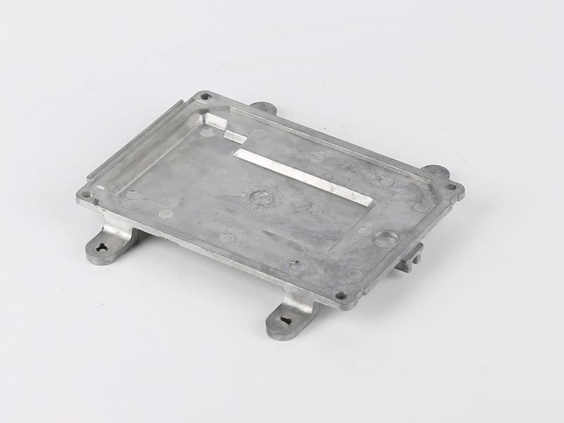
A machined billet part and a casting do not need identical internal geometry to perform the same job. A billet housing may begin as a thick block because the cutter must reach every pocket. A casting can place material near load paths, use draft, blend ribs into walls and form some external features directly. Conversely, a casting drawing may contain fillets, parting-line allowances and local pads that add needless machining if copied into a billet design.
Define the functions before seeking prices: load path, stiffness, pressure boundary, heat transfer, electrical continuity, bearing location, sealing, alignment, appearance and assembly. Mark the interfaces that truly control these functions. Suppliers can then propose one design for CNC machining and another for metal casting. Comparing functionally equivalent routes prevents a false cost result caused by forcing one process to imitate the other.
How the processes create shape
Machining removes material from a known product form
Machining starts with bar, plate, billet, extrusion or a near-net blank. Milling, turning, drilling, boring and related operations remove stock until the required surfaces remain. The starting product has its own grain direction, temper, residual stress and property data. Those conditions matter: cutting a thin asymmetric shell from thick stock can release stress and distort the part even when every tool path is accurate.
Tool access constrains geometry. Deep narrow pockets require long cutters, internal square corners are not produced by a rotating end mill, and features on many faces need extra setups or multi-axis access. Every setup adds datum transfer, fixture work and inspection exposure. Machining is flexible, but geometric freedom is not free.
Casting fills a tool and solidifies
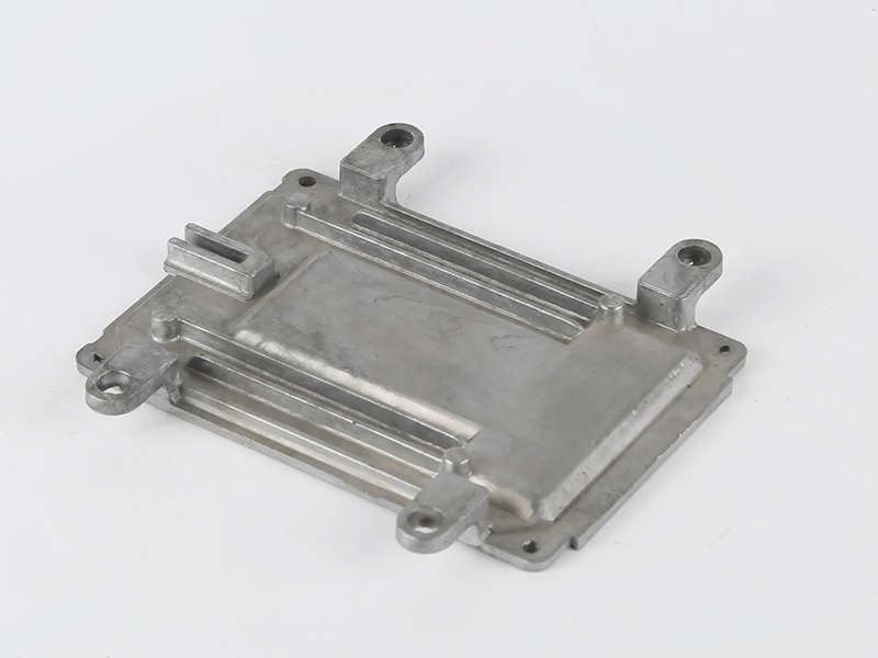
Casting puts liquid metal into a cavity and extracts a solid part. Process families differ in pressure, mold material, filling behavior and economic range, so "casting" is not one capability. For example, aluminum die casting can support repeatable complex shells when the alloy and geometry suit high-pressure filling, while other casting routes may be better for larger sections or different alloys.
The casting engineer must control fill sequence, air escape, metal temperature, die temperature, solidification, feeding where applicable, ejection and trimming. Parting lines, gates, overflows, ejector locations, draft and slides are production features, not cosmetic afterthoughts. A shape that looks easy in CAD may be difficult if a long thin flow path ends at a pressure-tight boss or if heavy sections feed shrinkage into a machined sealing face.
Compare geometry feature by feature
Casting tends to earn its tooling when it replaces expensive stock removal or assembly. Deep cavities, thin external fins, multiple bosses, curved envelopes and repeated ribs can be formed together. The benefit is greatest when the design follows casting rules: reasonably uniform transitions, useful draft, accessible parting, filleted junctions and machining stock only where needed.
Machining is attractive for prismatic parts, shafts, plates, accessible pockets and features whose locations are controlled directly from a small datum set. It also avoids draft and parting-line decisions. But a "simple" housing can become expensive when most of a costly block becomes chips, a cavity needs long-reach tooling, or several fixtures are required.
Undercuts deserve separate review. A machining undercut may need a special cutter or another orientation. A cast undercut may require a slide, loose piece or redesign. Ask each supplier to mark inaccessible or cost-driving features on the model. That annotated review carries more decision value than a generic process comparison.
Material choice is not identical between routes
The same broad alloy family does not guarantee the same grade, temper or properties. Wrought alloys are designed around rolling, extrusion, forging or other deformation routes. Casting alloys are formulated for fluidity, hot-cracking resistance, die interaction and solidification behavior. A drawing that specifies only "aluminum" or "zinc" is incomplete for either process.
Specify the required property at the component and location level: yield or proof behavior where relevant, elongation, hardness, conductivity, corrosion response, fatigue demand, service temperature and compatibility with joining or finishing. Then identify available product forms and casting grades. For compact high-detail parts, a zinc die-casting route may offer geometric advantages, but it should be selected only after density, environment, coating and load are accepted.
Do not transfer handbook values directly into a finished-part promise. Direction, section thickness, heat treatment, solidification rate, porosity, machining, surface condition and test orientation can change the evidence needed. Require the supplier to state the material specification, delivered condition and verification method.
Mechanical performance needs a load case
It is inaccurate to say that a machined part is inherently stronger merely because it was machined. Machining changes shape; the starting material and its processing history provide the baseline properties. It is equally inaccurate to assume that every casting is weak. A suitable casting can carry its intended load when alloy, geometry, process and acceptance are designed together.
For a fatigue-sensitive bracket, examine load direction, stress concentration, surface condition and likely defect location. For a pressure housing, examine pore connectivity, wall transitions, machined openings and the leak-test condition. For a thermal enclosure, stiffness and heat path may govern before nominal tensile strength does. The process decision follows the failure mode.
Use analysis to identify critical regions, then place validation there. Tensile coupons, hardness readings, sections, radiography, computed tomography, pressure testing or fatigue testing answer different questions. The drawing and control plan should say which evidence is required; "inspection included" is too vague.
Tolerance is a feature-level decision
CNC equipment can position cutting tools precisely, but achievable tolerance still depends on part size, tool reach, fixture rigidity, wall compliance, thermal state, datum structure and measurement method. Casting likewise has process capability that varies with alloy, tool condition, feature location, section and trimming. A universal tolerance value for either process is not a responsible basis for procurement.
Classify dimensions into three groups. First are as-cast or general machined features that only need clearance or appearance. Second are assembly dimensions that must maintain a defined relationship. Third are critical characteristics tied to safety, sealing or functional performance. Apply tight controls to the third group and selected interfaces in the second. Leaving every CAD dimension at a default tight tolerance creates cost without improving the product.
A hybrid route is often the clean answer. Add stable machining pads and establish a cast datum strategy, then use post machining for bores, threads, O-ring faces or bearing seats. Confirm how the casting will locate in the fixture and how much stock remains after casting variation.
Separate surface function from appearance
Machined surfaces carry tool marks whose pattern depends on operation, feed, cutter condition and subsequent finishing. Cast surfaces reflect the mold, filling and release conditions, plus trimming and handling. Neither is automatically ready for a cosmetic product. Define visible zones, allowable discontinuities, color, gloss, texture, edge condition and any sealed or electrically contacting areas.
Finishing can alter the process choice. A coating may hide color variation but expose sink, pores or poor edge preparation. A sealing face may need machining even if the remaining surface is accepted as cast. A route that includes powder coating needs agreed pretreatment, masking, film requirements and adhesion or corrosion validation for the actual environment.
Build the cost model from real operations
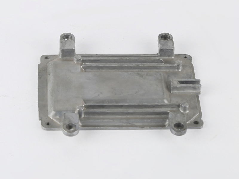
Machining cost is driven by material blank, purchased product form, programming, fixtures, setup, cutting time, tool consumption, deburring, inspection, scrap and capacity. Casting cost includes engineering, die and trim tooling, sampling, casting operations, trimming, secondary work, inspection, maintenance and yield. Freight, packaging and inventory policy belong in both models.
Do not compare only casting piece price with machining cycle price. Include amortized tooling under the expected demand scenario, and test more than one scenario. A forecast can rise, fall or end early. A design revision may require a program change, a fixture change, a tool insert modification or a new die. The commercial model should show who owns those costs.
Decision input | CNC machining effect | Casting effect | Evidence to request |
|---|---|---|---|
Geometry | Tool access, setups and stock removal | Parting, filling, solidification and ejection | Annotated DFM for each route |
Demand | Recurring machine and setup time | Tooling spread across accepted parts | Scenario quote by forecast and lot pattern |
Critical features | Direct machining and fixture control | Cast allowance plus selective machining | Datum, capability and inspection proposal |
Material | Blank form, condition and chip value | Castability, recovery and defect controls | Exact specification and delivered condition |
Change risk | Program or fixture rework | Insert, slide or die rework | Revision assumptions and change charges |
Quality risk | Distortion, burrs and datum transfer | Porosity, shrinkage, fill and trim variation | Control plan and validation evidence |
Volume matters, but there is no universal breakpoint
Higher repeated demand can make dedicated casting tooling economical, but no fixed unit count works across all parts. A small intricate component and a large multi-slide housing do not carry the same die investment or cycle economics. Likewise, machining cost per part can fall when fixtures, programs and tool paths mature.
Ask for the cumulative cost equation behind each quote. Include accepted quantity rather than shots or machine starts, because yield and inspection disposition affect delivered cost. Compare at expected demand, a downside case and an upside case. The crossover is where the modeled totals meet, provided both routes satisfy the same acceptance criteria and delivery pattern.
When demand is uncertain, low-volume manufacturing by machining may preserve cash and design flexibility. That does not mean it remains economical after the product stabilizes. Establish a review trigger based on actual demand, machining capacity and design maturity rather than a generic internet threshold.
Design maturity can outweigh piece price
A casting die commits to draft, parting, gates, overflows, ejectors, slides and shrinkage assumptions. Changes after steel is cut can be limited or expensive. Machining programs are generally easier to revise, although new stock, workholding or inspection can still be required. Early in development, this flexibility has value.
A practical transition is to machine prototypes for fit and functional learning while engineers develop the production casting concurrently. Do not treat a billet prototype as complete validation of the casting. It can verify envelope, interfaces and some loads, but it does not reproduce cast microstructure, draft, porosity, surface, residual stress or process variation.
Consider tooling and capacity as supply assets
A casting quote should define die scope, cavity count, inserts, slides, trim equipment, sampling, ownership, storage, maintenance, expected repair decisions and transfer restrictions. Tool life cannot be promised from material name alone; alloy, thermal cycle, geometry, cooling, surface treatment, process settings and maintenance all contribute.
Machining also uses production assets: fixtures, soft jaws, gauges, cutting tools, programs and qualified machines. For repeated demand, verify alternate capacity and change-control rules. A low fixture charge does not remove the risk of relying on one spindle type, one probing routine or one experienced operator.
The supplier's tool and die making review should connect tool architecture to part features and maintenance access. Procurement should understand which components are replaceable and which revisions would affect the main die.
Quality planning differs by process
Machining control focuses on material identity, fixture location, tool wear, burrs, thermal drift, distortion and measurement. Casting control adds melt condition, shot or pour parameters, tool temperature, venting, lubrication, solidification, trim and internal discontinuities. Sampling frequency should follow risk and demonstrated stability rather than assuming either process is automatically consistent.
Agree the defect language before production. A cosmetic pore, a leak path and a structurally relevant discontinuity are not the same condition. Define zones and acceptance methods. Use the available testing and inspection equipment only where it answers a specified question; equipment lists do not replace a control plan.
When a cast-plus-machined route wins
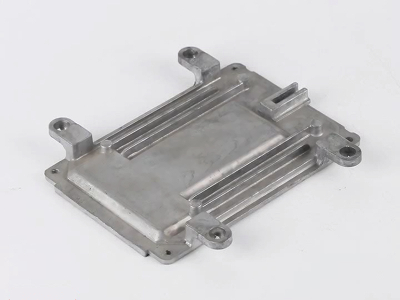
The hybrid route is strong when most volume can be formed economically but a few interfaces demand precision. Typical candidates include housings with machined bearing bores, pump bodies with sealed faces, brackets with controlled mounting datums, heat sinks with connector or fastener features, and valve bodies with machined passages.
Design the two processes together. Provide machining stock without creating a heavy hot spot. Keep critical areas away from gates, ejector damage or uncertain parting flash where practical. Choose datums that can be located repeatably on a casting, and specify how material condition will be supported during clamping. An apparently cheap casting can become an expensive machined blank if variation forces probing, custom support or repeated cuts.
A defensible decision sequence
Write the functional and acceptance requirements without prescribing a process unless regulation or prior validation requires one.
Separate critical interfaces from general shape and cosmetic zones.
Confirm exact material options and available product forms for both routes.
Request route-specific DFM, including a hybrid proposal where appropriate.
Build total-cost scenarios using forecast, lots, yield, inspection, finishing, tooling and revision assumptions.
Identify the likely failure modes and assign evidence to each one.
Validate prototypes and production-intent samples for what they actually represent.
Freeze the process, drawing revision, control plan and change rules before repeat production.
RFQ inputs that allow a useful comparison
Send a controlled 3D model and dimensioned drawing with revision, annual and lifetime demand scenarios, order pattern, target alloy or property requirements, service environment, load cases, appearance zones, finish, joining, cleanliness, traceability and packaging. Identify critical characteristics and the required inspection or test evidence. State whether tooling ownership, spare inserts, capacity reservation or phased delivery matters.
Ask each supplier to return assumptions, exclusions, material form, proposed process steps, subcontracted operations, tooling scope, first-article plan, production control plan and change impact. A review through an engineering team should produce marked-up features and open questions, not merely a piece price.
For a stable high-demand program, request the capacity and replenishment assumptions behind mass production. For an evolving program, price revisions and smaller releases explicitly. The selected route should remain sensible under the demand and change scenario the business can actually support.
Choose the route that controls the real constraint
Choose CNC machining when design flexibility, direct feature control, material product form or limited demand dominates. Choose casting when near-net integration and repeated output justify process-specific tooling. Choose casting plus machining when the economical shape and the precision interfaces belong to different processes.
The final approval should rest on a route-specific drawing, cost model and validation plan. That makes the decision traceable when demand, design or quality requirements change. It also prevents a common sourcing error: selecting a process from a slogan, then paying later to make the part compatible with it.
FAQ
Can Newway provide material certification reports for copper die castings?
What are the main differences between Zamak 3 and Zamak 5? How to choose?
What is the minimum wall thickness achievable for zinc alloy die castings?
Is zinc alloy die casting suitable for outdoor applications? How about its corrosion resistance?
What is the typical production lead time for zinc alloy die castings?