Reliable and Durable: Die Casting Solutions for Industrial Machinery and Heavy Equipment
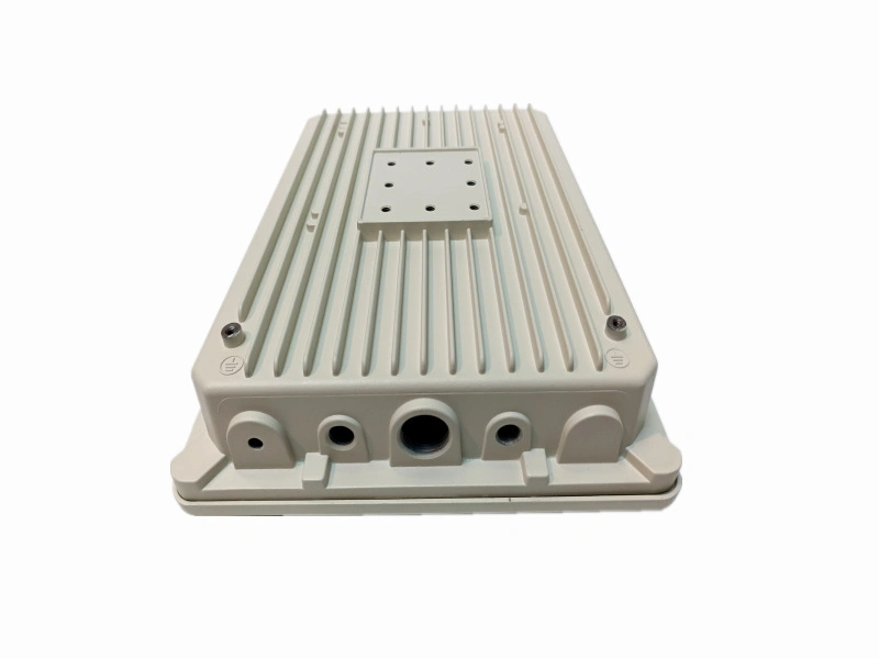
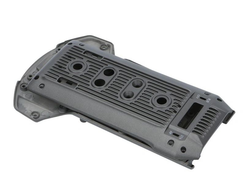
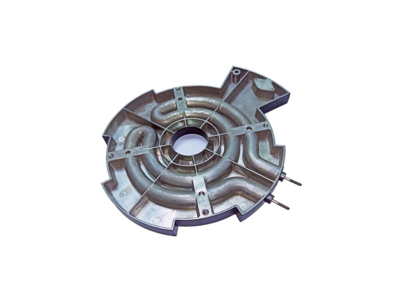
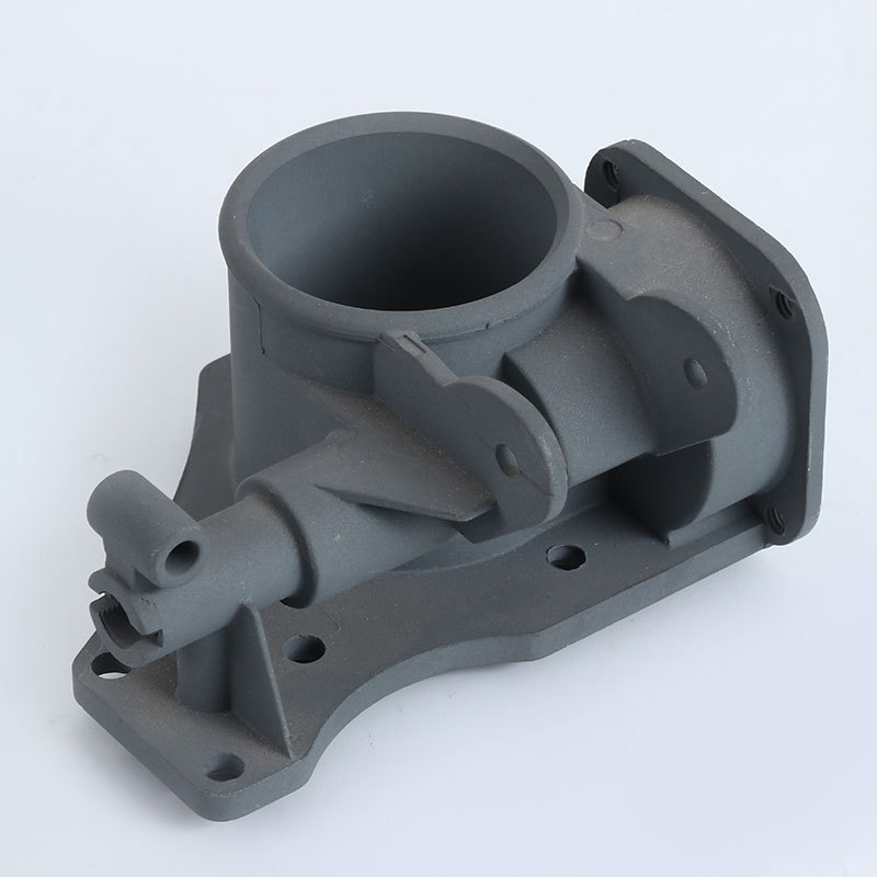 Die casting can provide reliable industrial-machinery components when integrated geometry, controlled material and casting integrity, machined interfaces, surface protection, and production evidence match the machine's actual duty. It is often screened for motor and gearbox housings, pump covers, valve and actuator bodies, control enclosures, brackets, covers, oil-management parts, handles, sensor bodies, and selected structural supports. It is not automatically suitable for every hydraulic pressure boundary, impact-loaded member, lifting function, or safety-critical structure.
Heavy equipment is not one environment. Mining dust, agricultural fertilizer, construction impact, factory washdown, compressor vibration, outdoor condensation, hydraulic oil, cutting fluid, and engine heat create different failure mechanisms. Reliability must be defined by function and maintenance context. A catalog alloy value, salt-fog duration, or tool shot count cannot demonstrate uptime in the field.
Define the machine duty before the part
State whether the component serves mining, construction, agriculture, material handling, energy, pumps, compressors, machine tools, conveyors, process equipment, or another system. Record normal, startup, shutdown, stall, jam, overload, impact, transport, maintenance, and foreseeable misuse conditions. Include force, torque, pressure, acceleration, vibration spectrum, duty, temperature, fluid, contamination, mounting, and required life.
Trace loads through shafts, bearings, gears, cylinders, valves, castings, fasteners, frames, and foundations. Identify whether the casting merely encloses a mechanism or locates and retains load-bearing elements. A motor cover, gearbox bearing housing, hydraulic manifold, and lifting bracket need different material, integrity, inspection, and validation decisions.
Define failure in operational terms: leakage, bearing misalignment, loose joint, cracked mount, lubricant loss, contamination entry, electrical fault, excessive temperature, seized mechanism, unsafe release, or unplanned downtime. Mark characteristics whose failure can cause secondary machine damage or personnel exposure. Those consequences determine design margins, controls, tests, and service instructions.
Select die casting where integration has value
Die casting can combine bearing supports, ribs, bosses, oil channels, drain features, connector walls, cooling fins, mounting feet, guards, labels, and assembly datums. Consolidation may remove welded brackets, machined blocks, fasteners, seals, and fixtures. This can reduce tolerance accumulation and operations when all functions fit a castable and inspectable design.
Integration also concentrates consequence. A pore opened at a machined gallery, shifted bearing center, damaged tool insert, or cracked boss can reject a component that carries many functions. Large specialized tools and machines can create capacity and repair dependencies. Compare conforming output, containment, spare strategy, field replacement, and downtime rather than nominal part count.
Other routes may be better. Forgings and wrought stock can suit shafts and highly loaded compact members; fabrication can suit large low-volume frames; ductile iron or steel castings can suit mass, damping, wear, and temperature needs; extrusion can suit long constant sections. Evaluate feasible finished assemblies under equal duty and service conditions.
Choose material and process route together
Aluminum die casting is commonly screened for motor, gearbox, pump, control, cover, and bracket applications where integrated geometry, lower density, heat spreading, and corrosion-system options are useful. A380, ADC12/A383, A360, A413, AlSi12, A356, and AlSi10Mg-type names do not describe one route or condition. Gravity, low-pressure, high-pressure, squeeze, semi-solid, and heat-treated routes can deliver different structures and properties.
Zinc die casting can fit compact latches, controls, sensor bodies, small gears, fittings, and mechanisms where detail, wear interface, finish, and stable small geometry matter. Density, sustained load, temperature, creep or relaxation, aging, lubricant, and corrosion must be considered. ZA and Zamak families require exact process and condition review.
Copper alloys, steel, stainless, iron, polymers, and engineered inserts may better serve local wear, conductivity, chemical, bearing, thread, or high-load functions. Some copper-alloy components are more practical as machined, forged, or separately cast elements. Hybrid interfaces require retention, galvanic, thermal-expansion, lubrication, fretting, sealing, inspection, and repair evidence.
Design load paths around cast integrity
Porosity, shrinkage, oxide films, inclusions, cold shuts, cracks, flash, and tool damage have different consequences by location. Mark zones around bearing seats, threaded bosses, fatigue paths, pressure boundaries, deep machining, seals, fasteners, and impact points. Define acceptable discontinuity types and evidence from the function instead of applying one generic porosity limit to the entire part.
Use DFM and engineering review to coordinate walls, ribs, fillets, bosses, parting, gates, overflows, vents, vacuum where used, cooling, slides, ejectors, trim, machining stock, and inspection. A rib can improve stiffness while creating a hot node or inaccessible cleaning pocket. A thick boss can support a fastener but concentrate shrinkage.
Published tensile values and separately cast specimens are screening inputs. They may not represent a gate region, heavy node, thin wall, machined surface, local oxide film, or field temperature. When analysis uses material data, identify alloy, route, condition, section, specimen location, orientation, surface, temperature, and scatter. Correlate high-consequence predictions with representative components.
Engineer fatigue, vibration, and impact
Continuous load and vibration require a defined spectrum. Mean stress, amplitude, frequency, multiaxial state, startup, resonance, impacts, temperature, corrosion, surface, defects, joints, and preload all affect fatigue. Tensile strength does not provide a universal endurance limit. Develop loads from measurement, machine models, duty data, and credible upset cases.
Geometry and assembly often control vibration behavior. Housing stiffness, bearing support, fasteners, foundation, motor and gear excitation, hydraulic pulsation, imbalance, and attached equipment determine modes. Analyze the complete boundary conditions and validate with strain, acceleration, modal, endurance, or functional measurements where appropriate.
A coating does not seal micro-porosity into a fatigue-proof structure, and ordinary blasting should not be assumed to create a controlled beneficial residual-stress state. Remove burrs and stress raisers, protect surfaces from corrosion and wear, maintain joint preload, and validate production-intent parts. Inspect after testing for hidden boss cracks, fretting, fastener movement, and bearing shifts.
Control hydraulic and lubricant boundaries
Pressure capability depends on pressure history, proof and burst requirements, pulsation, temperature, fluid, wall and port geometry, local casting integrity, threads, plugs, seals, machining, contamination, and failure consequence. A die-cast cover or low-pressure gallery is different from a high-energy manifold. The design authority must approve route and acceptance for each boundary.
Place gates, vents, overflows, high-risk discontinuity zones, and deep machining away from critical boundaries where possible. Post-machining can establish bores, spool features, seal lands, ports, threads, and bearing seats, but can expose pores or create burrs. Plan stock, fixtures, tool path, washing, inspection, and leak reaction together.
Cleanliness is functional. Chips, flash, abrasive, release residue, machining coolant, coating, fibers, and corrosion debris can damage valves, pumps, bearings, and seals. Define extraction or particle methods, limits, flushing, drying, preservation, packaging, and assembly handling. A part that passes a leak test can still fail a hydraulic system through contamination.
Manage bearings, gears, fasteners, and wear
Bearing fits depend on load direction, ring behavior, temperature, housing stiffness, material expansion, assembly, lubrication, and service. A generic press fit can distort a thin cast bore or lose preload. Control related bores and shoulders through a stable datum plan, then verify assembled rotation, torque, alignment, temperature, and retention.
Gearbox performance depends on centers, shafts, bearings, housing deflection, gear quality, lubrication, temperature, and joint preload. A precise free-state layout does not prove contact pattern under torque. Test backlash, contact, noise, vibration, leakage, and thermal behavior under representative duty.
Threads and inserts require local integrity, engagement, seating, preload, relaxation, corrosion, repeated maintenance, and repair rules. Steel fasteners in aluminum or zinc introduce galvanic and thermal questions. Define torque method, lubricant, locking, washers, allowed reuse, field tools, and damaged-thread disposition.
Qualify temperature, contamination, and corrosion
Industrial temperature exposure must include peak, sustained, gradients, dwell, cycles, load, creep or relaxation, aging, lubricant, seals, electronics, coating, and dimensional function. Melting point is not a service limit. Validate material and assembly behavior at the actual component temperature and time.
Corrosion depends on humidity, condensation, salt, fertilizers, coolants, cleaners, oils, acids, alkalis, process vapors, metal couples, electrical potential, crevices, scratches, drainage, and time. Define failure as pitting, section loss, coating failure, seized threads, leakage, increased contact resistance, contamination, or appearance only where appearance matters. Flat salt-fog coupons do not reproduce fastened, machined, dirty field assemblies.
Dust, mud, fibers, chips, slurry, and abrasive particles affect cooling, seals, joints, and wear. Design drainage and cleaning access. Protect vents and cable entries, avoid traps, and consider pressure equalization. Ingress performance belongs to the assembled enclosure with covers, seals, glands, vents, torque, and aging.
Use surface treatment as a system
Conversion coatings, anodizing where alloy and function permit, paint, powder coating, plating, sealers, and controlled bare or machined zones can support corrosion, wear, identification, cleaning, insulation, or electrical contact. No treatment universally extends industrial service life. Select substrate, preparation, full layer stack, film distribution, masks, cure, damage, repair, and acceptance together.
Separate barrier surfaces from wear contacts, seal lands, bearing seats, threads, grounding pads, and thermal interfaces. Thick layers change fits and preload; coating under a fastener can relax; chipped edges can concentrate corrosion; anodizing can change dimensions and fatigue-sensitive surfaces. Validate the assembled and damaged conditions relevant to service.
Mechanical preparation removes scale or creates texture but can embed media, expose pores, round edges, and contaminate passages. Tumbling does not reach every internal gallery. Polishing can reveal defects. Clean and inspect after each risk-relevant operation, and protect the finish through assembly, storage, shipping, and field installation.
Validate durability with a risk table
Industrial function | Dominant risk | Evidence before release |
|---|---|---|
Gearbox or motor housing | Bearing alignment, vibration, heat and lubricant leakage | Datums, loaded deflection, endurance, thermal and leak tests |
Hydraulic cover or valve body | Connected porosity, pulsation, machining burr and contamination | Integrity zones, cleanliness, proof/leak and functional cycling |
Outdoor control enclosure | Ingress, corrosion, grounding and thermal load | Aged assembly ingress, corrosion, electrical and temperature tests |
Dynamic bracket or support | Fatigue, impact, joint slip and stress concentration | Load spectrum, material/defect basis, joint and component endurance |
Serviceable mechanism | Thread damage, wear, contamination and wrong reassembly | Maintenance cycles, torque, wear, instructions and field inspection |
Design for maintenance and field repair
Industrial equipment is opened, washed, lubricated, adjusted, struck, lifted, and repaired under imperfect conditions. Provide access for tools, plugs, filters, bearings, seals, connectors, and inspection. Protect precision and sealing surfaces from common service damage. Define lifting and support points outside the casting unless the casting and complete procedure are approved for that function.
Specify replaceable wear elements where economical. A steel sleeve, bearing insert, sacrificial cover, or replaceable threaded insert can protect the main casting. Confirm retention and repair. Welding, impregnation, metal filler, peening, blending, re-machining, coating touch-up, and thread repair can alter integrity; each needs approved limits and validation.
Field traceability should support containment and parts selection. Mark part number, revision, cavity or lot as required without creating stress or corrosion sites. Preserve records for material, tool, process, machining, finish, inspection, rework, and shipment at the level needed by warranty and service.
Control tooling and production stability
Die life is a project result, not a fixed property of aluminum or zinc. Thermal checking, gross cracking, erosion, soldering, washout, slide wear, insert movement, cooling blockage, corrosion, and dimensional or cosmetic loss can end useful life. Alloy temperature and chemistry, shot energy, geometry, local heat flux, tool steel, heat treatment, surface treatment, cooling, lubrication, cycle interruptions, maintenance, and acceptance all matter.
Define useful life by acceptable production, not by the tool still closing. Identify high-risk inserts and surfaces, inspection frequency, dimensional and visual trends, maintenance limits, repair methods, spare inserts, and replacement plan. Record shots together with process interruptions and maintenance; a counter alone does not explain tool condition.
Production controls should connect material and melt, die thermal state, shot, vacuum where used, spray, cooling, ejection, trim, machining, finish, inspection, and packaging to product characteristics. Identify cavities. Establish warm-up, restart, abnormal process, nonconformance, containment, and change rules. Revalidate after repairs that affect load, pressure, datum, seal, or appearance zones.
Build evidence from samples to production
Validation should follow the actual risk chain. Early samples can establish geometry access, assembly sequence, and obvious leakage or stiffness issues, but hand-finished samples do not represent production variation. Production-intent trials should use the nominated alloy, tool state, cavity, shot process, machining fixtures, cleaning route, surface system, fasteners, seals, and assembly controls. Record deviations instead of treating a visually acceptable sample as proof of the final process.
Choose evidence by failure mechanism. Dimensional layouts establish datum relationships; radiography or sectioning can investigate selected internal zones; leak, proof, cleanliness, torque, thermal, vibration, endurance, corrosion, ingress, and functional tests answer different questions. No single inspection proves general durability. Sampling frequency and acceptance must account for consequence, method capability, cavity differences, process stability, and the possibility that destructive tests cannot screen every production part.
Release evidence should connect drawing characteristics to process controls and machine-level performance. Keep approved boundary samples, test configurations, measurement programs, material and finish records, and change history. When production moves between machines, cavities, inserts, material sources, machining lines, finish suppliers, or packaging methods, assess which evidence is no longer representative and repeat the affected validation.
Close the loop with field failures
Warranty data becomes useful only when the failed component retains context. Record machine model, serial, operating hours, duty, environment, maintenance, fluid, overload event, installation, symptoms, and previous repair. Preserve fracture faces, deposits, wear debris, seals, fasteners, and mating parts. Cleaning or forcing a seized assembly apart before examination can erase the mechanism.
Separate initiation from consequence. A loose fastener may create housing fretting; bearing misalignment may heat lubricant and damage a seal; blocked cooling may distort a bore; coating damage may start corrosion at a joint. Compare field evidence with retained parts and production records by lot, cavity, tool repair, machining line, finish batch, and assembly state. Corrective action should address the demonstrated cause and define containment, verification, recurrence monitoring, and documentation updates.
Feed findings back into drawings, control plans, maintenance instructions, spare strategy, and the next design. This closes the gap between a casting that passes release inspection and a machine component that remains serviceable under real industrial use.
Calculate weight and cost at assembly level
Aluminum can reduce mass relative to denser material, but feasible sections, ribs, inserts, fasteners, machining stock, corrosion allowance, and local reinforcement determine finished mass. Weight matters differently in mobile equipment, rotating guards, service-lift parts, counterweighted structures, and fixed bases. Convert mass change into fuel, payload, handling, inertia, transport, or installation value using the machine model.
Die casting can reduce cost through near-net shape and feature integration at stable demand. It can also add tool, specialized machine, machining, finish, inspection, maintenance, scrap, spare, and change costs. Compare complete assemblies and credible demand, yield, design-change, downtime, and service scenarios. A lower piece price that creates field failures is not economic.
Tooling investment must be evaluated against lifecycle quantities, variants, spare-part tail, design maturity, capacity, and continuity. CNC, fabrication, sand or permanent-mold casting, forging, and iron casting may be better at other volumes or duties. Use total lifecycle cost and reliability evidence rather than assuming high volume selects die casting.
Prepare an industrial component RFQ
Provide controlled geometry, machine and component function, normal/upset loads, pressure and pulsation, vibration spectrum, duty, impact, temperature, fluids, cleanliness, contamination, corrosion, ingress, wear, bearings/gears/fasteners, safety consequence, maintenance, target life, demand, variants, material/process restrictions, finish, machining, inspection, tests, traceability, capacity, service, and change requirements.
The supplier should return exact material and route, assumptions, DFM exceptions, load/pressure/integrity zones, gate/vent/cavity concept, machining and datum plan, cleanliness route, full finish system, samples, inspection, sub-tiers, tooling failure/maintenance plan, spares, capacity, continuity, traceability, change triggers, validation support, and open risks. Use inspection resources only where method, access, resolution, uncertainty, and decision rule match the characteristic.
A reliable industrial die casting is a controlled component whose material, local integrity, interfaces, surface, cleanliness, and production process remain fit for the real machine duty and service environment. Durability is demonstrated through representative evidence and field-informed controls, not declared from alloy family, coating hours, or tool shot counts.
FAQs
What are the most durable die casting materials for industrial components?
Can die cast parts handle continuous mechanical loads and vibration?
How do surface treatments enhance durability in industrial environments?
What is the typical die life in heavy equipment applications?
How does die casting reduce cost and weight in structural parts?