Most Commonly Used Metal Casting Processes for Manufacturers
Introduction
Metal casting is one of the most versatile and widely used manufacturing processes in modern industry. From complex automotive components to intricate aerospace parts, casting enables manufacturers to create durable, high-performance products with exceptional design flexibility.
With numerous casting processes available—each offering unique advantages in cost, precision, material compatibility, and production volume—choosing the right method is critical for achieving optimal results. This guide explores the most commonly used metal casting processes, helping manufacturers select the best option based on their project’s technical requirements and business objectives.
 Overview of Metal Casting Processes
Understanding the fundamentals of metal casting is key to selecting the most suitable process for your manufacturing needs. While all casting methods share the core principle of forming metal by pouring molten material into a mold, each process offers distinct advantages and trade-offs in terms of design flexibility, performance, cost, and scalability.
What Is Metal Casting?
Metal casting is a manufacturing process where molten metal is poured into a mold cavity and solidified into a desired shape. After cooling, the part is removed from the mold and typically undergoes post-processing to achieve final dimensional and surface specifications.
Casting enables the production of complex geometries, integrated features, and near-net shape parts—often with minimal material waste compared to subtractive processes like machining.
Common industries using casting include:
Automotive: engine blocks, transmission housings, structural components
Aerospace: turbine blades, brackets, and high-performance structural parts
Consumer electronics: precision housings, heat sinks
Industrial equipment: pumps, valves, and large structural castings
Energy: turbine components, pipe fittings, and structural supports
Key Factors in Selecting a Casting Process
Selecting the appropriate casting process depends on several interrelated factors:
Part complexity: intricate geometries or internal features may require investment casting or high-pressure die casting (HPDC).
Production volume: High volumes justify tooling investment in HPDC, while sand casting offers flexibility for prototypes and low-volume production.
Material requirements: aluminum alloys, zinc alloys, copper alloys, and specialty metals perform differently across casting processes.
Performance targets: mechanical strength, fatigue life, thermal conductivity, or corrosion resistance.
Cost targets and delivery schedule: balancing upfront tooling costs with per-part production cost and project lead time.
By understanding these variables, manufacturers can make informed decisions about which casting method best supports their product goals.
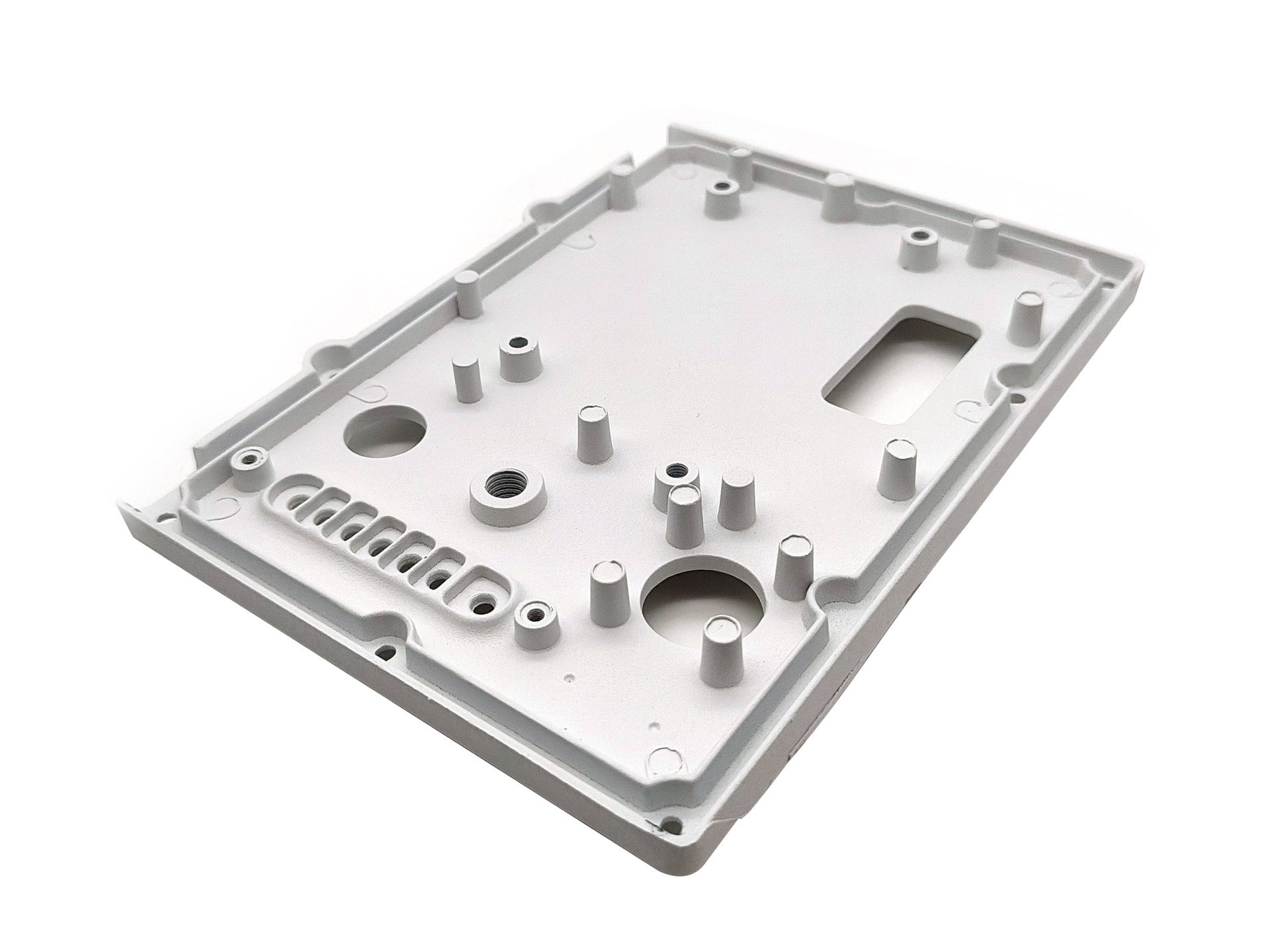
High Pressure Die Casting (HPDC)
Process Overview
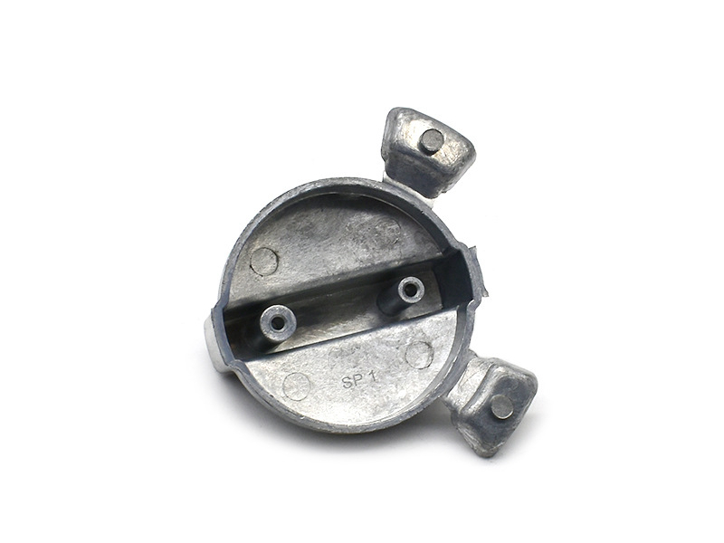
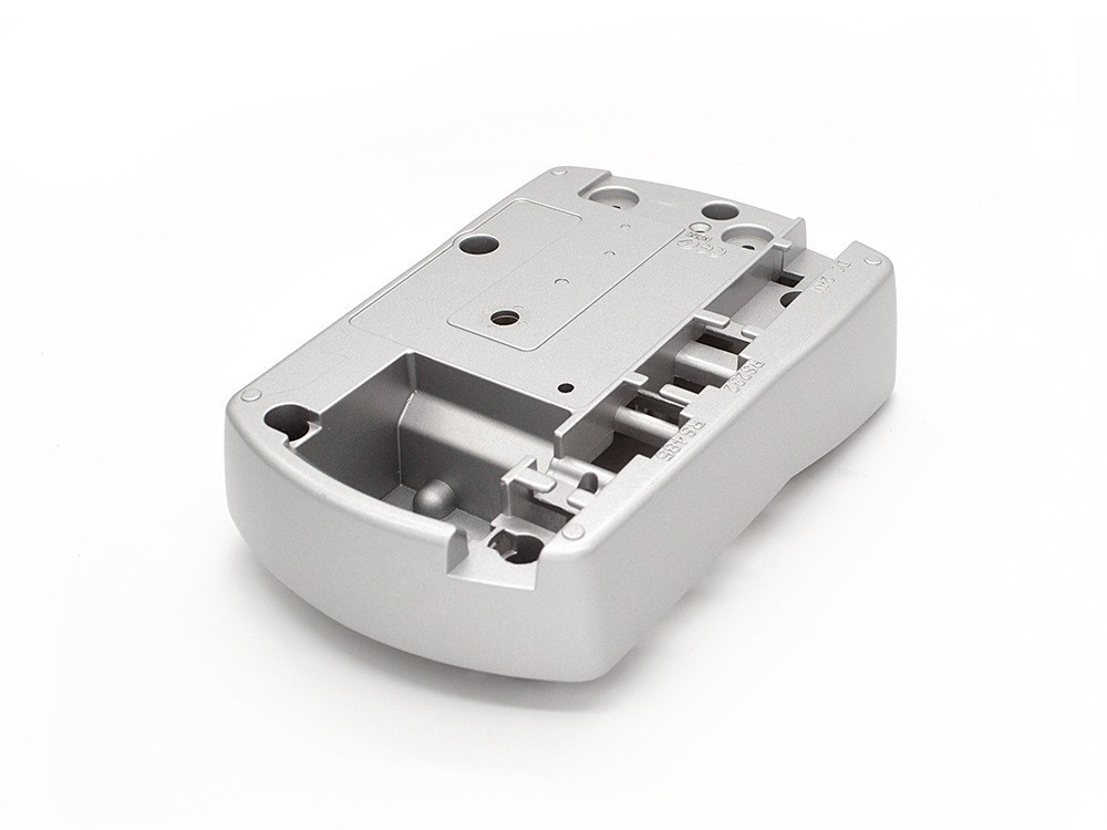
High-pressure die casting (HPDC) is one of the most efficient and widely used metal casting processes for producing high-volume, precision components. In HPDC, molten metal is injected into a hardened steel mold cavity under high pressure—typically 1,000 to 20,000 psi—at very high speeds. The metal solidifies rapidly, after which the mold opens and the finished part is ejected.
Key characteristics of HPDC include:
High cycle rates (5 to 15 seconds per shot)
Excellent dimensional accuracy and repeatability
Fine surface finish with minimal post-processing
Suitability for thin-walled parts and complex geometries
Common materials used in HPDC include:
Aluminum alloys: A380, A413, A360, ADC12—lightweight with good strength-to-weight ratio
Zinc alloys: Zamak series—excellent surface finish and castability
Advantages and Limitations
Advantages:
Extremely high production efficiency—ideal for mass production
Low per-part cost once tooling is amortized
Excellent surface finish suitable for premium consumer products
High-dimensional precision reduces post-machining requirements
Suitable for thin-wall, lightweight designs
Limitations:
High tooling costs—often $20,000 to $100,000+ per mold
Best suited for high-volume projects due to tooling investment
Possible porosity due to trapped gases—advanced techniques like vacuum HPDC help mitigate this
Not suitable for very large parts due to equipment limitations
Typical Applications
HPDC is a go-to process for industries that demand large quantities of dimensionally consistent parts:
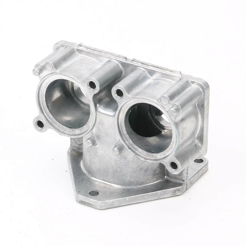
Automotive components: transmission housings, engine brackets, structural supports, heat sinks
Consumer electronics housings: laptop bodies, mobile device frames, speaker enclosures
Industrial electrical enclosures and lighting components
Medical device housings and precision hardware
When project volume and product design align with HPDC’s strengths, it offers an unparalleled combination of speed, cost-efficiency, and quality.
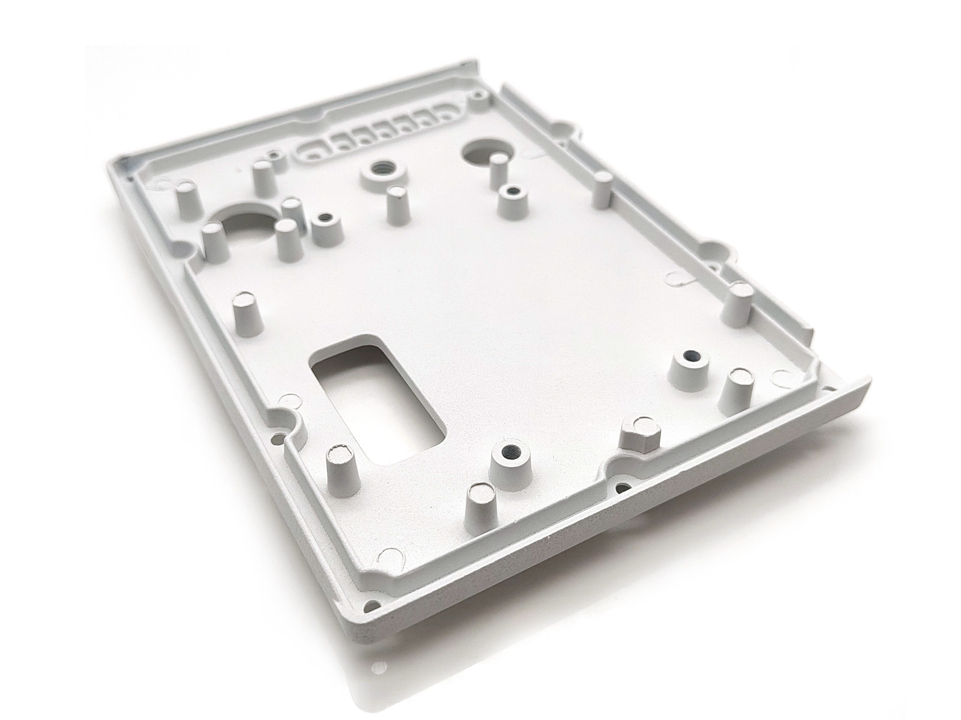
Gravity Die Casting (Permanent Mold Casting)
Process Overview
Gravity die casting, also known as permanent mold casting, involves pouring molten metal into a reusable metal mold under the force of gravity, rather than injection under high pressure. The metal slowly fills the mold cavity, solidifies, and is then removed. Unlike sand casting molds, which are single-use, gravity casting molds can produce thousands of parts before needing replacement.
Gravity casting achieves better mechanical properties and surface finishes compared to sand casting, and it is more cost-effective for medium-volume production runs where high-pressure die casting tooling costs may not be justified.
Common materials used include:
Aluminum alloys: A356, A319, AC4C, AlSi7Mg—offering good strength and corrosion resistance
Copper alloys: Brass and bronze grades for wear-resistant and conductive parts
Advantages and Limitations
Advantages:
Lower tooling cost compared to HPDC
Longer mold life and better dimensional consistency than sand casting
Superior mechanical properties—denser structure and fewer internal defects
Suitable for moderate wall thicknesses and medium complexity parts
Limitations:
Slower cycle times than HPDC
Less suitable for extremely thin-walled or highly complex geometries
Manual pouring can introduce variability without proper process control
Typical Applications
Gravity die casting is widely used for mid-range production volumes and structural parts where mechanical performance is a priority:
Lighting components and heat sinks
Automotive suspension components and brake housings
Pump bodies, valve housings, and other fluid-handling components
Industrial motor housings and machinery parts
Gravity casting bridges the gap between sand casting flexibility and HPDC productivity, making it an excellent choice for many industrial applications.
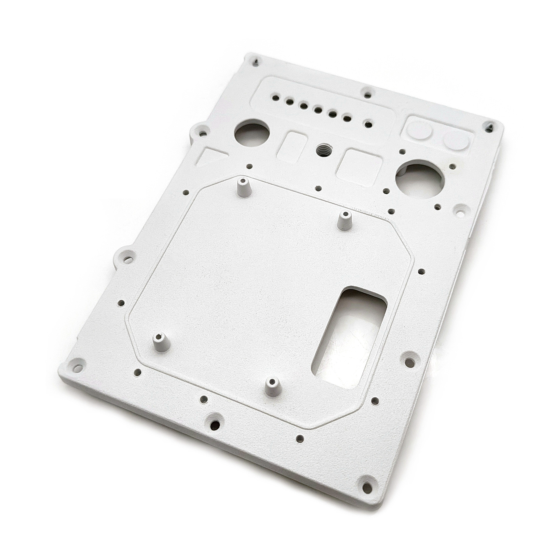
Sand Casting
Process Overview
Sand casting is one of the oldest and most versatile metal casting processes, widely used across industries for both prototype development and full-scale production of large or complex components.
In sand casting, a mold is formed by packing sand around a pattern of the desired part shape. After the pattern is removed, molten metal is poured into the cavity and allowed to solidify. Once cooled, the sand mold is broken apart, and the casting is removed for post-processing.
Sand molds are expendable, allowing for highly flexible and economical tooling, especially for low-volume manufacturing or large-scale castings.
Common materials include:
Aluminum alloys
Iron and steel alloys
Copper alloys
Specialty alloys for high-temperature or corrosive environments
Advantages and Limitations
Advantages:
Very low tooling cost—patterns are inexpensive to produce
Flexible—easily adapted for prototype and short-run production
Suitable for large components (hundreds of kg or more)
Compatible with a wide range of metals
Limitations:
Slower cycle times (mold creation + cooling)
Lower surface finish quality and dimensional accuracy compared to high-pressure die casting (HPDC) or gravity casting
Higher labor content per part
Typically requires post-machining to achieve critical tolerances
Typical Applications
Sand casting remains a cornerstone process for:
Heavy equipment and industrial machinery components
Energy sector parts—turbine housings, pump bodies, valve components
Prototypes and engineering validation parts
Large automotive and truck components
Specialty, one-off, or low-volume production where tooling investment in permanent molds is not justified
For large, low- to medium-complexity parts, sand casting provides unmatched flexibility and cost-effectiveness.
Investment Casting (Lost Wax Casting)
Process Overview
Investment casting—also known as lost wax casting—is a precision casting process that produces intricate components with excellent surface finish and dimensional accuracy. It is ideal for manufacturing complex parts that are difficult or impossible to produce using other methods.
The process begins with creating a wax pattern of the part, which is then coated with a ceramic slurry to form a mold. After curing, the wax is melted and drained, leaving a hollow ceramic shell. Molten metal is then poured into the shell, allowed to cool and solidify, after which the ceramic is broken away, and the casting is cleaned and finished.
This method enables the production of near-net shape parts with minimal post-machining.
Common materials include:
Aluminum alloys
Stainless steels
Superalloys (nickel- and cobalt-based)
Copper alloys and precious metals
Advantages and Limitations
Advantages:
Exceptional surface finish—Ra as low as 1.6–3.2 μm
Excellent dimensional accuracy—tight tolerances achievable
Capable of producing very complex geometries and thin-walled parts
Minimal material waste—high material utilization
Broad material compatibility—including exotic alloys
Limitations:
Higher per-part cost compared to high-pressure die casting (HPDC)
More labor-intensive process
Slower production cycle—suitable for low to medium volumes
Complex mold preparation requires skilled craftsmanship
Typical Applications
Investment casting is the preferred process for:
Aerospace components—turbine blades, structural brackets
Medical implants and surgical tools
High-end industrial components requiring precision and a superior surface finish
Military and defense parts
Intricate consumer electronics components with premium surface requirements
For parts where precision, design complexity, and performance are the priority, investment casting offers an unmatched solution.
Other Specialized Casting Processes
In addition to the widely used methods already covered, several specialized casting processes offer unique advantages for certain applications. These techniques help manufacturers achieve specific performance targets, superior material properties, or precision features.
Low Pressure Die Casting
Low-pressure die casting (LPDC) is a process where molten metal is pushed upward into a permanent mold under controlled low pressure.
Produces dense, high-integrity parts with fewer gas porosities
Excellent for structural components requiring high mechanical strength
Suitable for aluminum alloys and magnesium alloys
Applications:
Automotive wheels and suspension components
Aerospace structural parts
High-performance industrial products
LPDC offers a balance of good mechanical properties and superior consistency—ideal for safety-critical applications.
Centrifugal Casting
In centrifugal casting, molten metal is poured into a rotating mold. Centrifugal force distributes the metal evenly against the mold wall.
Produces parts with a very fine grain structure and high material density
Virtually free of internal porosity
Ideal for rotationally symmetrical components
Applications:
Pipes and tubes
Bushings, sleeves, and rings
Bearings and liners for high-wear applications
Centrifugal casting is highly valued in the energy, oil & gas, and heavy industrial sectors.
Vacuum Die Casting
Vacuum die casting enhances high pressure die casting (HPDC) by pulling a vacuum inside the mold during injection.
Reduces gas entrapment, improving mechanical strength and ductility
Significantly reduces porosity, which is critical for parts subject to fatigue or pressure loads
Often used for thin-wall, complex geometries in lightweight alloys
Applications:
Structural automotive parts (e.g., shock towers, subframes)
Aerospace components requiring structural integrity
High-end electronics housings and enclosures
Vacuum die casting is often paired with advanced inspection techniques to verify part quality for mission-critical applications.
Superalloy Casting Methods
When manufacturing superalloy components for high-temperature, high-stress environments, such as aerospace turbines or industrial gas turbines, advanced casting methods are required to achieve optimal mechanical and thermal properties.
The following superalloy casting techniques control grain structure to improve creep resistance, fatigue life, and overall performance:
Standard investment casting of superalloys with fine, equiaxed grain structures
Cost-effective and suitable for non-critical turbine and structural components
Good balance between mechanical properties and manufacturability
Directional Solidification (DS) Casting:
Controls solidification to align grains along the primary stress axis
Reduces transverse grain boundaries, improving fatigue and creep performance
Widely used for turbine blades, vanes, and nozzle guide vanes in hot sections
Eliminates grain boundaries entirely—component is grown as a single crystal
Maximizes creep resistance and thermal fatigue life under extreme temperatures (>1000°C)
Critical for advanced aero-engine turbine blades and high-performance gas turbines
These methods require specialized mold design, precise thermal control, and proprietary process expertise. Vacuum investment casting combined with advanced inspection (X-ray, CT, metallography) ensures the integrity of these mission-critical components.
Applications:
Aircraft engine turbine blades and vanes
Industrial gas turbine hot section components
Rocket engine components
Heat shields and advanced structural components for space and defense
Superalloy casting represents the pinnacle of precision casting technology, where material science and casting engineering converge to enable next-generation aerospace and energy systems.
.jpg)
.jpg)