English

Advanced Aluminum Die Casting for Energy-Efficient LED Lighting Fixtures
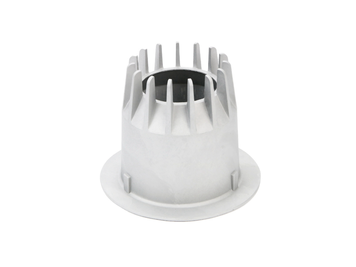
Table of Contents
Define what energy-efficient means for the luminaire
Map the thermal-resistance chain before DFM
Decide where die casting adds real value
Select alloy for the whole fixture, not one property
Compare thermal architecture options before tooling
Design fins for airflow and castability
Control the LED module and driver interfaces
Engineer outdoor sealing and condensation
Choose finishes by thermal, optical, and environmental function
Coordinate tooling, secondary work, and assembly
Validate thermal performance in production-intent luminaires
Qualify production with measurable characteristics
Prepare a decision-ready LED housing RFQ
Release the luminaire system, not an isolated housing
FAQs

Aluminum die cast LED fixture housing reviewed for thermal path, fins, module interface, optics, sealing, surface finish, and production validation Aluminum die casting can support energy-efficient LED lighting by combining a heat-spreading body, convective surfaces, optical and driver mounts, environmental enclosure, and installation features in one repeatable component. It does not make an LED electrically efficient by itself. Its value is keeping LED junctions, boards, drivers, seals, and optics within their validated temperatures while limiting interfaces, mass, assembly variation, and avoidable power derating.

The result depends on the full path from semiconductor junction to ambient air: LED package, solder and board, thermal interface material, machined or controlled casting pad, casting base, fins, surface condition, orientation, airflow, enclosure temperature, and nearby driver losses. A visually impressive fin array can perform poorly if the module contact is uneven, fins cannot fill in the die, warm air recirculates, paint insulates the contact pad, or the sealed volume traps driver heat. Tooling should begin only after the thermal, optical, electrical, ingress, safety, appearance, and manufacturing requirements agree.

Define what energy-efficient means for the luminaire

Start with system targets rather than a housing temperature in isolation. Provide LED module and driver, input power, dimming strategy, light-output target, optical losses, ambient range, installation orientation, duty cycle, enclosure, airflow, insulation or ceiling conditions, and required life or maintenance model. Identify the temperature limits and measurement points supplied by the LED, driver, gasket, lens, adhesive, connector, and coating manufacturers. The luminaire owner must decide which limits govern release.

High temperature can reduce light output, shift color, accelerate lumen depreciation, shorten driver or capacitor life, soften seals, age adhesives, and trigger current reduction. Low temperature, rapid cycling, condensation, or uneven expansion can also matter. State whether the product is a downlight, streetlight, high-bay, wall washer, floodlight, automotive module, hazardous-area fixture, or decorative luminaire; the available airflow, orientation, dirt, weather, service access, and approval path differ.

Separate energy consumption from maintained performance. A cooler LED may permit operation closer to its intended current and reduce thermal derating, but housing design does not change the driver efficiency or optical efficiency automatically. Acceptance should measure input power, light output, relevant temperatures, controls behavior, and photometric stability together under defined ambient and mounting conditions.

Map the thermal-resistance chain before DFM

Represent every layer between the junction and ambient as a thermal resistance and identify uncertain contacts. The LED and board supplier may provide junction-to-case or test-point relationships, but the fixture team still owns board-to-housing interface, heat spreading through the casting, convection and radiation to the environment, and interactions with the driver and optics. Use losses at the actual operating point; nominal lamp wattage alone is not the heat load.

Contact resistance often dominates a good alloy. Define board flatness, casting-pad flatness and texture, thermal interface material type and applied condition, compression or fastener pattern, clamp stiffness, screw torque, allowable voids, insulation requirements, and rework. A thick pad or excessive interface material can erase gains from alloy conductivity. A bare grounding or heat-transfer pad must also coexist with corrosion protection and electrical safety.

Thermal models need realistic boundaries: ambient temperature, air velocity, gravity orientation, surrounding ceiling or wall, solar load, nearby fixtures, dust loading, coating emissivity, internal air, lens absorption, and driver dissipation. Validate model assumptions on instrumented assemblies. Correlation matters more than a polished color plot.

Decide where die casting adds real value

Aluminum die casting is attractive when a fixture needs repeat quantities and can benefit from a single body containing heat-spreading ribs, external fins, LED and driver mounts, lens seats, cable paths, gasket channels, aiming features, hinges, bosses, and installation brackets. Consolidation can remove thermal joints and assembly errors. It can also concentrate several failure modes in one part, so each integrated feature needs casting, machining, finishing, assembly, and inspection controls.

Compare the route with extrusion, stamped sheet, machined plate, gravity casting, forged or cold-formed heat sinks, and hybrid assemblies. Extrusion may provide long straight fins and favorable conductivity with simple cross-sections. Sheet can be light and economical for low heat loads. Machined wrought material can suit low volumes and early thermal validation. HPDC becomes compelling when three-dimensional integration, repeatability, wall complexity, sealed geometry, or part consolidation offsets tooling and process constraints.

Do not force every heat sink into one casting. A hybrid fixture may use a die-cast enclosure plus an extrusion, vapor chamber, heat pipe, graphite interface, or separate spreader where heat density demands it. The decision table should compare thermal result, optical envelope, mass, assembly, sealing, corrosion, tooling, quantity, repair, supply risk, and total cost.

Select alloy for the whole fixture, not one property

Thermal conductivity is important, but alloy ranking cannot ignore die fill, strength, corrosion, machining, porosity, finish, availability, and supplier process stability. A380 or ADC12-family materials are common production candidates where castability and general mechanical performance fit. A360 may be screened where its corrosion/casting balance is useful. AlSi12-family alloys may support fluidity for some geometries. Exact designation, chemistry, product standard, and measured condition must be confirmed because names and published values vary by region, process, and specimen.

Alloy selection should use thermal data that represents the proposed composition and state. Casting porosity, intermetallic phases, section thickness, melt condition, and local cooling can make a production part differ from a handbook value. Higher-conductivity specialty die-casting alloys may be worth evaluating, but price, mechanical margins, process window, joining, finishing, recycling controls, and qualified supply need equal attention.

Outdoor, coastal, chemically cleaned, or condensation-prone fixtures require corrosion review. Higher conductivity does not compensate for pitting at a seal land or galvanic attack around stainless hardware. Indoor decorative fixtures may instead prioritize appearance and color consistency. Document the weighted requirements so the supplier understands why one trade is acceptable and another is not.

Compare thermal architecture options before tooling

Architecture

Where it may fit

Primary risk

Release evidence

One-piece die-cast housing and heat sink

Three-dimensional fixtures needing integrated mounts, fins, seals, and optical features

Contact-pad control, fin fill, porosity, mass, trapped driver heat, concentrated tool-change risk

Production-intent thermal, dimensional, ingress, finish, and assembly validation

Die-cast enclosure plus extruded heat sink

Long straight fins or scalable heat-sink lengths with a complex enclosure

Added thermal interface, fasteners, corrosion couple, tolerance and assembly variation

Interface resistance, torque retention, aging, leak and lifecycle cost tests

Machined wrought prototype, die-cast production body

Early geometry and electronics integration before production tooling

Prototype conductivity, mass and fin geometry may overpredict production casting

Explicit prototype correlation plan and die-cast revalidation

Die casting with separate spreader or heat pipe

Localized heat flux that the casting alone cannot spread within the envelope

Bond quality, orientation sensitivity, long-term interface and supply variation

Worst-case assembly, cycling, vibration and end-product thermal tests

Sheet or polymer enclosure with separate thermal core

Low enclosure load, electrical isolation, low volume, or radio/optical requirements

More parts, thermal path complexity, creep, flammability, shielding or sealing

Complete luminaire safety, thermal, mechanical and environmental evidence

Design fins for airflow and castability

Fin area alone is not a performance metric. Fin height, thickness, spacing, base thickness, taper, orientation, surface condition, and surrounding clearance determine how much area is thermally active. Closely packed fins can restrict natural convection or fill with dust. Horizontal fins can trap warm air or water. A decorative shroud may recirculate exhaust air. Review the fixture in every permitted mounting orientation and with realistic nearby surfaces.

HPDC fins need draft, fill path, venting, ejection strength, and tool access. Very thin, tall, closely spaced fins may misrun, solder to the die, distort, break during handling, or create fragile tool steel. A thicker fin that fills consistently may outperform an idealized thin fin that is frequently incomplete. Gate and overflow locations should support the thermal base and fin roots without placing trim or porosity in the module pad, seal, or visible face.

Use flow simulation as a question generator, then confirm with trials and sectioning where risk justifies it. Track fin completeness, local porosity, warpage, weight, and thermal performance by cavity. If cosmetic fins are also visible, establish fill and appearance limits that do not hide a functional thermal problem.

Control the LED module and driver interfaces

The LED module pad needs a datum and inspection strategy tied to actual contact. Blanket casting tolerances are rarely enough, while blanket machining wastes cost and can expose porosity. Machine only where contact, optical alignment, seal, thread, or assembly function requires it. Tolerance planning should include coating and interface-material thickness in the final stack.

Driver placement deserves its own thermal budget. Mounting a driver in the coolest available zone, separating it from the LED hot spot, providing conductive paths where intended, and preventing trapped hot air can matter more than another external fin. Cable routing must avoid hot surfaces, sharp cast edges, optical shadows, and gasket crossings. Integrated standoffs need creepage, clearance, insulation, grounding, and fastener controls based on the finished product's safety design.

Optical alignment depends on lens seats, reflector position, LED board datum, window bond, and thermal movement. A housing can keep the LED cool and still fail beam distribution or glare requirements if stack variation moves the source. Thermal, optical, mechanical, and tooling teams should use the same datum scheme and review the assembly at cold and hot conditions.

Engineer outdoor sealing and condensation

An IP rating belongs to the complete tested luminaire, including housing, cover, lens, window bond, gasket, fasteners, cable gland, connector, vent, coating, torque, and assembly process. Choose the rating and test conditions from rain, jets, dust, temporary immersion, washing, or other exposure. IP65 does not demonstrate immersion, salt corrosion, UV aging, condensation control, or retained protection after years of opening and service.

Thermal cycling changes internal pressure and joint dimensions. A pressure-equalization vent can reduce differential pressure in some designs but becomes another water, contamination, and assembly interface. Model condensation and drainage as well as external entry. Keep gasket grooves, lens bonds, cable entries, and vents away from water traps and direct hot-air paths. Select seal materials against temperature, compression set, UV, chemicals, and expected opening cycles.

Casting porosity exposed by machining can create leak paths. Coordinate gating, local stock, seal-land machining, allowable discontinuities, impregnation policy where approved, and production leak screening. Correlate a pressure-decay or other factory screen with the formal ingress failure modes; one test does not automatically substitute for the other.

Choose finishes by thermal, optical, and environmental function

A dark, high-emissivity surface may increase radiative heat transfer under some conditions, but radiation is only one part of the thermal balance. A coating can also add resistance at a module pad, change fin dimensions, bridge vents, alter grounding, or absorb solar energy. Keep specified thermal contacts bare or account for the qualified layer, and protect exposed aluminum appropriately. Measure the finished fixture rather than assigning a universal cooling benefit to black paint or anodizing.

Outdoor polyester powder, liquid primer/topcoat systems, sealed anodic finishes on compatible alloys, conversion pretreatment, painting, polishing, or other decorative processes may be considered. Surface-treatment choice depends on substrate chemistry, UV, corrosion, appearance, touch, abrasion, cleaning, heat, masking, repair, and regulations. Die-cast intermetallics and porosity can make anodized color and texture differ from wrought aluminum.

Issue color, gloss, texture, viewing distance, lighting, master sample, defect zones, rack marks, parting-line and ejector limits, masking, film, adhesion, cure, corrosion, and packaging requirements. Decorative approval under one light source can fail in the installed scene, so use relevant illumination and viewing geometry.

Coordinate tooling, secondary work, and assembly

Tooling must protect the thermal base, optical datums, seal path, visible surfaces, and fin fill at the same time. Gate, vent, overflow, ejector, slide, insert, parting, cooling, trim, and cavity decisions should be reviewed on the final machined and coated model. Plan replaceable inserts where product variants or high-wear details justify them, while accounting for flash and witness limits.

Post-machining, washing, pretreatment, coating, insert installation, thermal-interface application, module fastening, sealing, optical assembly, and electrical tests form one process chain. Define where parts are cleaned after cutting and before electronics, how pores or residues are accepted, and how coatings avoid threads and contacts. An assembly error can dominate casting quality.

Design fixtures and gauges for the features that drive module contact, beam alignment, sealing, and mounting. Track cavity and tooling revision through machining, finish, and end-of-line results. If one cavity runs hotter or leaks more frequently, aggregate lot averages will conceal it.

Validate thermal performance in production-intent luminaires

Thermal validation should use specified LED and driver lots, production-intent boards, interface material, castings, machining, finishes, lenses, seals, cables, fasteners, torque, and installation. Measure at locations that allow junction or component temperature to be assessed using the component manufacturer's method. Record ambient, stabilization, orientation, input power, control state, airflow, mounting, surrounding surfaces, and sensor attachment. Report uncertainty and repeatability.

Test worst credible combinations: high ambient, low input voltage if it increases driver loss, maximum LED current, unfavorable bin or component variation, blocked airflow, dirt allowance if specified, tight enclosure, solar load, alternate orientation, and dimensional extremes. Thermal cycling, vibration, ingress exposure, coating aging, or repeated service may change contact and sealing, so repeat functional tests when the risk analysis requires retained performance.

Photometric and electrical checks should accompany thermal work. Confirm light output, power, current regulation, dimming, color, beam, driver protection behavior, and abnormal conditions under the governing product requirements. A lower housing temperature is not enough if the optical path loses more light or the driver operates inefficiently.

Qualify production with measurable characteristics

First articles must represent the proposed alloy source, production die and cavities, casting machine/process window, trim, machining program, cleaning, finish sub-tier, interface material, hardware, seals, optics, assembly, and packaging. Record chemistry or material lot, cavity, significant process data, dimensions, porosity evidence at critical zones where specified, coating batch and cure, repairs, torque, leak result, and thermal/functional test lineage.

Pilot builds should expose variation across cavities, startups, maintenance states, machining tools, coating racks, operators, and component lots. Use process capability only for stable, well-defined measurements. A polished hand-selected sample is useful for design review but not production approval. Establish reaction plans for incomplete fins, module-pad defects, warpage, coating contamination, color variation, leaks, poor contact, and thermal outliers.

Change control should cover alloy/composition window, metal source, machine/site, die and inserts, gates/vents, release agent, machining source/program/tool, wash, pretreatment, coating formulation/color/cure/sub-tier, thermal interface, LED/board/driver, gasket, adhesive, lens, fastener, torque, assembly site, test method, and packaging. Define which changes require DFM, thermal correlation, photometric, ingress, safety, appearance, or full requalification.

Prepare a decision-ready LED housing RFQ

Provide controlled models and drawings; luminaire type and markets; LED, board and driver data; heat loads and temperature limits; input power and controls; optical stack and datums; ambient, orientation, airflow, mounting and solar conditions; IP and corrosion exposure; electrical safety, grounding and insulation; loads and vibration; appearance masters; service model; quantity; approvals; inspection; validation; traceability; packaging; and change requirements.

Ask the supplier to return the exact alloy and standard, property basis, casting route, DFM and flow risks, gate/vent/cooling concept, thermal-pad and fin controls, machining stock, surface layer stack, mask/rack locations, critical-zone defect plan, sealing assumptions, sub-tier scope, prototype route, production validation, test methods, acceptance, repair, capacity basis, timing gates, and exceptions. Links to die-cast heat-sink planning can support the discussion, but the supplier response must address this luminaire.

Release the luminaire system, not an isolated housing

Advanced aluminum die casting supports energy-efficient LED lighting when it turns a verified thermal and enclosure architecture into repeatable production. The engineering sequence is direct: define system efficiency and temperature limits, model the complete thermal chain, choose the right manufacturing architecture and alloy, design castable airflow surfaces, control module/driver/optical/seal interfaces, validate the finished luminaire, and hold the approved process through production changes.

The housing should be accepted on measured luminaire performance, not on fin count, alloy brochure conductivity, black color, or a generic IP claim. When production-intent assemblies meet thermal, photometric, electrical, ingress, mechanical, appearance, and lifecycle requirements at defined worst conditions, aluminum die casting has earned its role.

FAQs

  1. What aluminum alloys are most effective for LED lighting applications?

  2. How does die casting improve thermal management in LED systems?

  3. Can die cast housings meet IP65 or higher ingress protection standards?

  4. What finishing options are available for decorative lighting components?

  5. What is the typical lead time for LED lighting prototype development?
Copyright © 2026 Diecast Precision Works Ltd.All Rights Reserved.