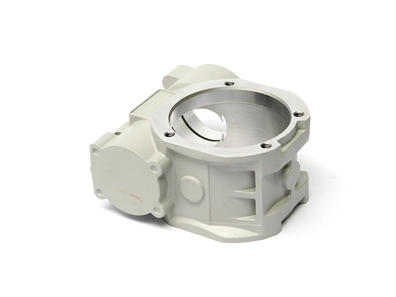
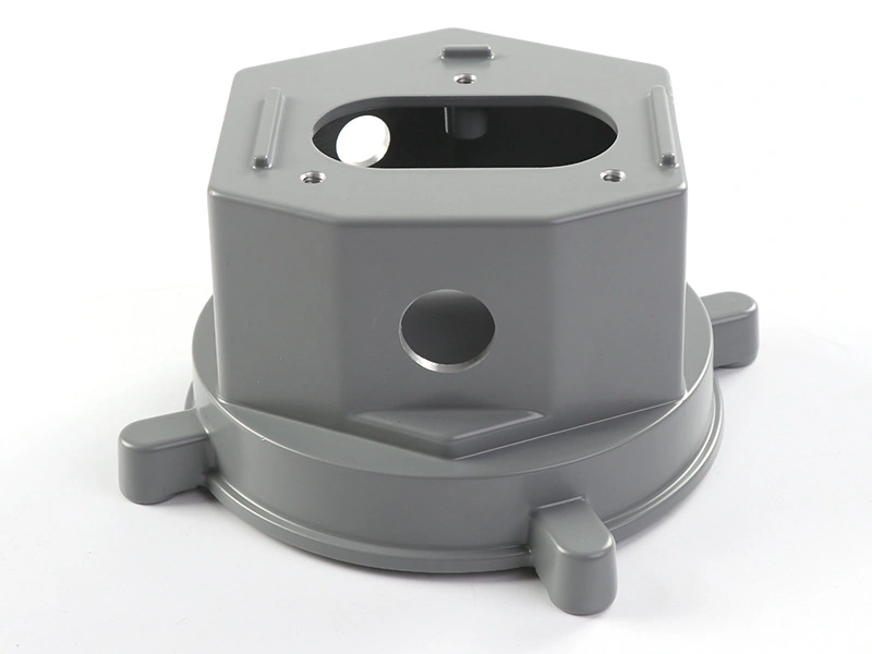
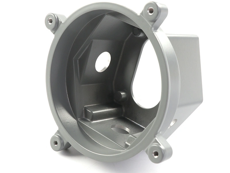
Durable and Corrosion-Resistant Aluminum Die Cast Parts for Marine Applications
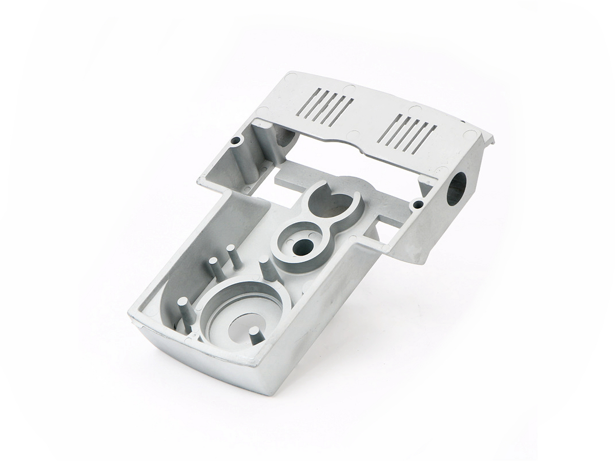 Aluminum die cast parts can be durable in marine applications, but only when the exposure, alloy, casting route, geometry, dissimilar-metal contacts, finish, seals, acceptance tests, and maintenance plan are engineered as one system. A coated housing mounted above deck is a different problem from an intermittently splashed pump bracket, a bilge component, or a continuously immersed load-bearing part. The words "aluminum," "marine grade," or "salt-spray tested" do not settle that distinction.
High-pressure die casting is most persuasive for complex covers, control housings, lighting bodies, sensor enclosures, heat-spreading frames, mounts, and other repeat-production parts where integrated ribs, bosses, cable entries, and sealing features create value. It may be the wrong route when the part requires a wrought marine alloy, very high structural ductility, weldability, thick-section soundness, or direct long-term immersion with little tolerance for coating damage. Buyers should select the complete material-process-finish architecture before tooling, then validate production-intent assemblies against the real use case.
Define the marine exposure before choosing an alloy
Start with location and wetting. Record whether the part is below deck, weather-deck exposed, inside a nominally sealed enclosure, in a splash or tidal zone, periodically washed, subject to condensation, or immersed. Identify natural seawater, brackish water, chlorinated water, deicing salt, cleaning chemicals, fuel, hydraulic fluid, and biological deposits separately. Salt concentration alone does not describe a corrosion environment; temperature, oxygen, wet-dry cycling, deposits, crevices, pollutants, and time between washdowns change the mechanism.
Then define function and consequence. Cosmetic staining on a removable cover is not equivalent to pitting at a gasket land, loss of section around a lifting point, corrosion under an electrical ground, or leakage into navigation electronics. State design life, inspection interval, allowable appearance change, dimensional limits, electrical continuity, thermal function, sealing requirement, loads, vibration, impact, and the result of a single-point failure. The acceptance plan should focus on the zones whose deterioration changes safety or function.
Installation details matter just as much. Identify fastener and mating-part materials, conductive gaskets, bonding straps, sealants, thread compounds, cathodic-protection systems, stray-current sources, shore-power conditions, and access for rinsing. Provide orientation and drainage direction. A laboratory coupon cannot represent a horizontal pocket that holds warm saltwater beneath a stainless washer.
Decide whether high-pressure die casting fits the part
Aluminum die casting can consolidate brackets, cooling fins, connector bosses, cable-routing features, mounting pads, and gasket channels into one repeatable body. That can reduce joints and loose hardware, but consolidation also concentrates risk: one casting defect or coating breach may affect sealing, alignment, heat transfer, and support at once. The DFM review must map each integrated feature to a casting, machining, finish, assembly, and inspection control.
Do not assume every aluminum alloy shown on a material list is suitable for conventional high-pressure die casting. Wrought 5xxx and 6xxx alloys often associated with boats are not direct substitutes for pressure-die-casting alloys. Some low-copper casting alloys are used through gravity, low-pressure, or other casting routes rather than the proposed HPDC cell. If a drawing names an alloy and process that do not fit together, resolve the conflict before quotation. Compare HPDC with gravity casting, low-pressure casting, machined wrought plate or extrusion, fabrication, and polymer or stainless alternatives against geometry, quantity, tooling, properties, finish, repair, and lifecycle exposure.
Pressure tightness also needs its own decision. HPDC may contain connected porosity or local oxide films even when external appearance is acceptable. A sealing enclosure can succeed through controlled filling and venting, local machining allowance, impregnation where approved, a barrier finish, gasket design, and assembly leak testing. None of those measures should quietly compensate for a structural or pressure-boundary requirement that the casting process cannot reliably meet.
Select alloy by chemistry, process, and finished condition
For die-cast marine parts, alloy selection is a trade among corrosion behavior, castability, mechanical needs, thermal function, machinability, finish response, availability, and process stability. A360 is commonly considered when corrosion performance is weighted more heavily than with higher-copper general-purpose alloys such as A380, while AlSi12-family alloys may offer useful filling behavior. Those are screening observations, not universal recommendations. Confirm the exact standard designation, composition limits, temper or as-cast condition, supplier route, and test basis; regional names are not always interchangeable.
Alloy data should be read against the proposed process and final part, not copied from an unrelated specimen or heat treatment. Copper content, iron-bearing intermetallics, silicon morphology, magnesium, impurities, recycled-metal controls, porosity, section thickness, and thermal history can affect corrosion and mechanical response. A nominal grade does not guarantee that a machined pore, trimmed edge, or coating defect behaves like an intact cast skin.
If the part is safety-related, continuously immersed, highly loaded, welded, or used in a classified marine system, involve the responsible naval architect, equipment authority, or classification body early. Their accepted material form, documentation, testing, and supplier approval may rule out an otherwise economical die-cast option. Do not label a part "marine grade" unless the purchase specification defines what that means and what evidence closes it.
Compare material and process options before tool release
Candidate route | Where it can be attractive | Marine risk to resolve | Evidence before release |
|---|---|---|---|
Low-copper aluminum HPDC plus qualified finish | Complex repeat-production housings, covers, mounts, lighting and control bodies | Porosity, exposed machined metal, galvanic couples, coating holidays, seal-land stability | Composition, casting trials, section review, finish coupons and parts, assembly leak and corrosion tests |
Gravity or low-pressure aluminum casting | Thicker sections or alloy/property combinations not suited to HPDC | Tooling and cycle economics, feeding defects, dimensional and machining allowance | Process-specific property, radiography or sectioning plan where justified, machined-part validation |
Machined wrought aluminum | Low volume, weldable marine alloy requirement, simple geometry or high ductility need | Material waste, machining cost, crevices at assembled features, finish on sharp edges | Mill records, machining capability, finish qualification, assembly corrosion test |
Stainless steel | Wear, fire, temperature, impact, or corrosion conditions favor the selected grade | Mass, cost, chloride grade selection, crevice corrosion, galvanic effect on adjacent aluminum | Grade and condition, fabrication/passivation route, coupled-assembly and load evidence |
Polymer or composite enclosure | Electrical isolation, low load, radio transparency, or corrosion avoidance | UV, creep, flammability, impact, sealing, thermal and shielding performance | Environmental aging and complete enclosure functional tests |
The table is a quotation gate, not a ranking. A buyer should document why the selected route meets the particular exposure and consequence with fewer unresolved risks than the alternatives.
Design out water traps, crevices, and uninspectable damage
Durability begins with geometry. Give exterior surfaces drainage in installed orientation, and check alternate attitudes during transport and service. Avoid blind pockets below ribs, deep counterbores that retain brine, sharp inside corners that are hard to pretreat, and narrow crevices that stay wet after the open surface dries. Provide drain paths that remain open after machining, coating, gasket installation, and cable assembly. A drain hole placed on a CAD low point can become ineffective when the vessel trims or the product is mounted differently.
Protect edges and transitions because finishes tend to thin or pull back there. Use practical radii, coating-accessible gaps, and hole designs that can be rinsed. Separate cosmetic and function-critical zones on the drawing. Masked grounding pads, threads, seal lands, press fits, and machined faces expose or interrupt the protective system; define how each is protected after assembly and how corrosion there will be inspected.
For load-bearing parts, evaluate corrosion allowance and stress concentration together. Pitting at a highly stressed fillet is more serious than equal surface loss in a broad unloaded wall. Do not solve a filling problem by thinning a critical wall without revisiting impact, fatigue, thread engagement, and corrosion damage. Production samples should be sectioned at suspected flow joins and thick-to-thin transitions when the risk analysis calls for internal evidence.
Control galvanic corrosion at every interface
Aluminum coupled to stainless fasteners, copper conductors, brass fittings, carbon fiber, nickel-plated parts, or other more noble materials can corrode rapidly when an electrolyte bridges the pair. Risk depends on potential difference, electrolyte conductivity, wet time, area ratio, geometry, and resistance of the electrical path. A small aluminum area electrically connected to a large noble surface is especially unfavorable. A generic compatibility chart does not account for those assembly details.
Controls may include nonconductive washers or sleeves, compatible sealants, isolated inserts, selected fastener finishes, barrier coatings, joint drainage, reduced noble-to-aluminum area, and deliberate bonding strategies. Electrical bonding and lightning or EMC requirements can conflict with isolation, so electrical and corrosion engineers must agree on where conductivity is required. Coating only the aluminum while leaving a large noble cathode exposed can produce severe attack at one holiday; the complete couple must be reviewed.
Verify the built assembly, including damaged and aged states. Test around fastener heads, cut edges, ground points, gasket breaks, connector shells, and repair areas. Installation instructions should identify approved hardware, isolation parts, torque, compounds, and replacement rules. An unapproved stainless washer introduced during field service can defeat a well-qualified joint.
Choose a surface system, not just a coating name
Marine protection is a layer stack: cast substrate, cleaning, mechanical preparation where used, conversion or anodic pretreatment where suitable, primer, topcoat or powder, sealants, masking, cure, handling, and repair. The right stack depends on immersion, UV, abrasion, color, electrical grounding, heat transfer, dimensional fit, alloy, porosity, and maintenance. A finish specification should name pretreatment and final system, not merely "powder coat black."
Sealed anodizing can be useful on compatible aluminum, but die-cast alloy chemistry and porosity can affect appearance, continuity, and dimensional growth. It should not be assumed equivalent to anodized wrought aluminum. Outdoor polyester powder systems can provide color and UV resistance when pretreatment, edge coverage, cure, and damage control are qualified. Liquid primer and topcoat systems may offer repair flexibility and tailored barrier performance. Selection must be confirmed with the finish supplier using the actual substrate and exposure.
Surface-treatment performance is sensitive to casting residue, release agent, trapped chemistry, exposed pores, blasting media, cleaning, rinse quality, bath control, film build, cure, and packaging. Validate representative castings, not only flat wrought coupons. Define allowed rack marks, contact points, touch-up, plugged holes, edge coverage, color variation, and rejection at corrosion-critical zones.
Engineer sealing as an assembly function
An IP rating belongs to a tested enclosure configuration, not to a bare casting. The cover, base, gasket, fasteners, cable glands, vents, connectors, windows, coatings, machining, torque, and assembly method all contribute. Select the required ingress level from actual exposure and the applicable edition of the governing test standard. IP65 addresses dust and water jets under specified conditions; it does not prove resistance to immersion, pressure cycling, salt corrosion, condensation, or long-term gasket aging.
Define gasket material from temperature, compression set, UV, fluids, and salt exposure. Set gland fill, compression range, joint stiffness, fastener spacing, torque method, surface texture, flatness, and acceptable casting/machining discontinuities through calculation and testing. Keep paint build and anodic growth out of critical fits or include them in the dimensional stack. Prevent coating steps or rework from rounding a seal edge or filling a designed vent.
Validate worst-case dimensional combinations, repeated opening, contamination, aged gaskets, thermal cycling, vibration, and assembly variation where relevant. Leak or pressure-decay testing can screen production assemblies, but the method, fixtures, stabilization, limits, calibration, and correlation to the required ingress test must be defined. A passed dry-air leak test does not automatically predict water entry through every path.
Plan tooling, casting, machining, and finishing together
Tooling decisions shape corrosion performance. Gate and overflow positions influence flow joins, entrapped air, oxide films, and where porosity appears after machining. Ejector marks, parting lines, trim edges, and overflows should not land on gasket surfaces or drainage-critical areas without a controlled finishing plan. Cooling and ejection must protect seal-land stability. DFM should show final machined and coated condition, not just the as-cast model.
Machining can remove the denser cast skin and expose pores. Identify every machined thread, O-ring groove, connector bore, grounding pad, and flat; assign datum strategy, stock allowance, defect acceptance, washing, and post-machining protection. Tolerance planning should reserve tight controls for interfaces that affect seal, load, alignment, or assembly. Blanket precision raises cost and may increase machining exposure without improving marine durability.
Finish racks, masks, plugs, and contact points need design space. Confirm that pretreatment can enter and drain from recesses without trapping liquid. Define whether inserts are installed before or after finish, how threads are protected, and how electrical contact is restored where required. Approve a complete route card from incoming alloy through packed part so that a sub-tier change cannot silently alter the surface system.
Turn corrosion testing into an acceptance plan
Accelerated salt tests such as ASTM B117 or ISO 9227 can compare process conditions and reveal some coating defects when the specimen preparation, scribing, exposure, and evaluation are specified. They do not convert directly into years at sea, and a test duration has no meaning without acceptance criteria. State specimen type, production lot, edge treatment, intentional scribe if any, orientation, inspection intervals, allowed blistering, underfilm creep, pitting, base-metal attack, adhesion, appearance, and post-exposure function.
Cyclic corrosion, UV/weathering, humidity, immersion, thermal cycling, abrasion, chemical splash, galvanic assembly exposure, and combined tests may represent the use case better than continuous neutral salt fog. Sequence matters: vibration may crack a finish before salt exposure, and UV may embrittle a topcoat before impact. Build a test matrix from failure mechanisms rather than requesting every familiar standard. Use controlled reference samples and retain pretest condition records.
Corrosion is only one release dimension. Verify alloy chemistry, casting defects at critical zones, dimensions, coating thickness and cure, adhesion, sealing, torque retention, electrical bonding or isolation, thermal behavior, load, and appearance as the drawing requires. Inspection resources must be matched to the characteristic, resolution, sampling, calibration, and acceptance method; an equipment list by itself is not evidence.
Qualify production and control changes
First articles should come from production-intent tooling, alloy supply, casting parameters, trim, heat or aging condition if used, machining, washing, finishing sub-tier, sealing components, assembly, and packaging. Record cavity, melt or lot, key process settings, machining program, finish batch, film measurements, gasket batch, torque, repairs, inspections, and test results. Hand-polished show samples or separately coated coupons cannot establish repeatability.
Use pilot quantity to expose variation across cavities, starts and stops, and finish racks or loads. Examine the locations where failures are likely, not just easy exterior faces. If impregnation, touch-up, local repair, or rework is allowed, qualify its limit and identify it in records. Decide whether repaired parts can enter safety-related, pressure, cosmetic, grounding, or seal zones.
Change control should cover alloy source or composition window, recycled-content practice where specified, casting site and machine, die repair, gate or vent, release agent, machining source or program, blasting media, cleaner, pretreatment chemistry, coating manufacturer/formulation/color, cure, finish sub-tier, gasket, fastener, sealant, packaging, and inspection method. Define notification lead time, evidence, approval authority, and disposition of existing stock. A visually identical coating reformulation can require renewed compatibility and corrosion work.
Design maintenance and field repair before production
Even a qualified marine surface will be scratched, cleaned, opened, and reassembled. State freshwater-rinse frequency where needed, permitted cleaners and tools, inspection zones, acceptable staining or coating damage, fastener replacement, gasket replacement, drain clearing, touch-up procedure, and retirement criteria. Make critical joints visible or accessible. A coating that performs well until the first service event is not a durable system.
Repair instructions must define surface preparation, approved material, cure conditions, overlap, environmental limits, and post-repair inspection. Some damaged anodized or conversion-coated systems cannot be restored in the field to the original condition. Mark areas where touch-up is cosmetic only and where exposed aluminum requires part replacement. Prevent repair materials from insulating required bonds, contaminating seals, blocking drains, or attacking gaskets.
Feed field findings back to manufacturing. Record corrosion location, installation, exposure, time, cleaning history, hardware, electrical conditions, damage, and photographs before destructive work. Distinguish coating failure, galvanic attack, crevice corrosion, casting discontinuity, mechanical wear, and maintenance error. That evidence supports a focused corrective action rather than a thicker unspecified coating.
Prepare an RFQ that suppliers can answer
The RFQ should include the 3D model and controlled drawing; installed orientation; wetting, immersion, temperature, UV, chemicals, cleaning, vibration, and electrical environment; function and consequence; loads; target life and maintenance; mating materials; grounding and isolation; ingress requirement; cosmetic zones; prohibited substances; annual and lifetime demand; traceability; inspection; validation; and change-notification needs. Mark corrosion-critical, sealing, load, heat-transfer, and electrical zones on the drawing.
Ask the supplier to return the proposed alloy designation and controlling specification, casting route, DFM risks, gate/vent concept, critical-zone defect controls, machining stock and exposed-surface plan, complete finish stack, mask and rack locations, sealing assumptions, sub-tier ownership, test matrix, acceptance criteria, sample traceability, rework limits, packaging, and open exceptions. Request evidence for the actual process scope rather than generic marine claims.
A defensible sourcing decision compares total risk and lifecycle cost: tooling, casting yield, machining, finish, testing, assembly, maintenance, repair, replacement, weight, and consequence of water ingress or corrosion. Aluminum HPDC earns its place when its integrated geometry and repeatability outweigh the controls needed for porosity, galvanic interfaces, surface protection, and service damage.
Release only a verified marine part system
Durable and corrosion-resistant aluminum die cast parts for marine applications are possible, but durability is conditional. Define the exact exposure, select a process-compatible alloy, remove water traps, control dissimilar-metal couples, qualify the full surface stack, engineer the enclosure assembly, inspect critical production zones, and validate representative aged and damaged conditions. Keep accelerated test results tied to their stated method and acceptance; never translate them into an unsupported service-life promise.
Release tooling and production only when the buyer and supplier agree on requirements, evidence, repairs, maintenance, and changes. That record makes the answer auditable: the part is suitable not because aluminum is broadly corrosion resistant, but because this alloy, geometry, process, finish, assembly, and control plan passed the acceptance case for this marine installation.
FAQs
What aluminum alloys are best suited for saltwater marine environments?
How does aluminum die casting compare to stainless steel in corrosion resistance?
Can marine die cast parts be sealed to IP65 or higher standards?
What surface coatings provide the best protection in coastal conditions?
What testing standards apply to aluminum parts used in marine systems?