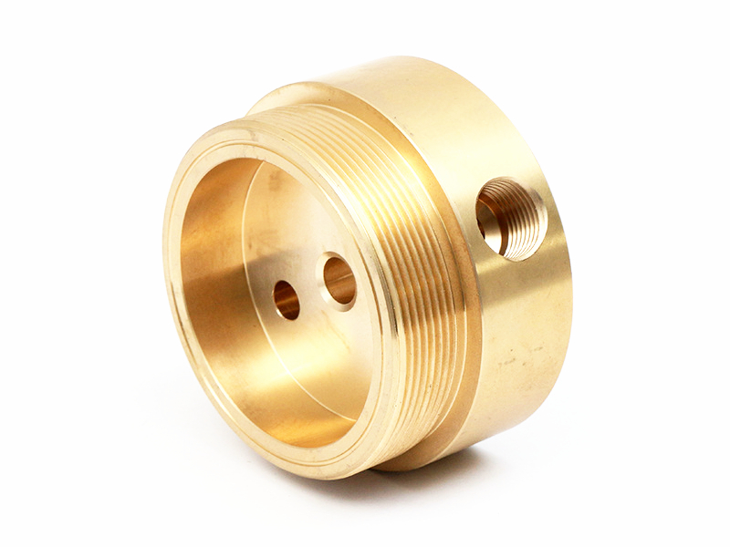
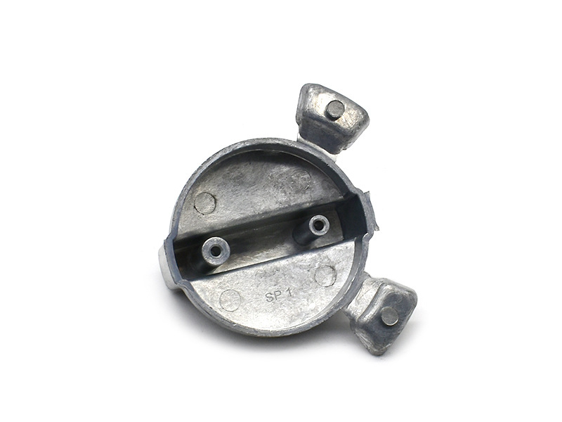
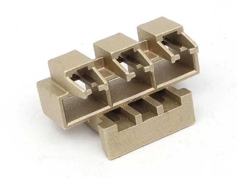
A high-strength copper-alloy die casting can be useful in an automotive cooling system when a compact heat path or integrated fluid-routing function offsets copper's mass, material cost and demanding casting conditions. It is not automatically the best choice for an EV cold plate, inverter base or coolant manifold. The exact alloy must exist in the intended cast product form, the internal passages must be manufacturable and inspectable, and the completed module must satisfy vehicle thermal, pressure, corrosion, vibration and electrical requirements.
Procurement should compare the finished thermal module rather than rank raw materials by conductivity. A credible copper die-casting proposal defines the heat source, coolant circuit, structural interfaces, seals, joining route and test plan. It also explains why copper-based integration is preferable to an aluminum casting, wrought copper assembly or mixed-material architecture for this vehicle location.
Battery modules, power electronics, electric motors, engines and transmissions impose different heat fluxes, allowable temperatures and failure consequences. A battery plate often values uniform cell temperature and electrical isolation. An inverter base may concentrate heat beneath semiconductor modules and depend on a controlled thermal interface. An electric-motor jacket must manage circular flow, structural loads and electrical boundaries. Engine and transmission circuits face different coolant or oil chemistry, contamination and temperature histories.
Describe the component's role before selecting metal. A solid thermal spreader does not need the same casting evidence as a pressure-containing cold plate. A coolant manifold is governed by distribution, port loads and leak integrity. A refrigerant chiller introduces a separate fluid, lubricant and pressure regime. Combining these under the phrase automotive cooling part encourages unsupported material and pressure claims.
Component concept | Route worth comparing | Main decision risk | Evidence before release |
|---|---|---|---|
Solid inverter or power-module heat spreader | Wrought plate, machined copper or near-net cast alloy | Bulk conductivity may be outweighed by contact resistance and flatness | Actual-condition material data and assembled thermal correlation |
Cold plate with wide shallow channels | Two machined/cast halves joined, or formed plate construction | Joint continuity, distortion, cleanliness and electrical consequence of leakage | Channel inspection, joint sections, leak/pressure and thermal-cycle tests |
Manifold with straight intersecting passages | Cast body plus drilling, plugs and machined ports | Burrs, plug joints and machining exposure in pressure zones | Passage inspection, cleanliness, plug qualification and final leak test |
Lightweight battery-pack plate | Aluminum die casting, extrusion, stamping or mixed material | Copper mass may consume vehicle benefit despite higher conductivity | Module-level temperature uniformity, pressure drop, mass and cost comparison |
Refrigerant distributor or chiller housing | Qualified casting, forging/machining or brazed construction | Fluid/lubricant compatibility, pressure class and joint cleanliness | Material-system qualification and completed boundary testing |
A die-cast route is strongest when integration removes joints or machining while retaining inspectable passages. Long tortuous microchannels, extremely thin unsupported walls or a material designation unavailable as casting stock may point elsewhere. Keep an alternative route open through DFM instead of forcing every cooling concept into a one-piece casting.
C11000 and C12200 are familiar in sheet, tube and other wrought thermal products. C17500 and C18200 are often discussed using wrought and heat-treated property data. Those values do not prove that the same designation can be pressure die cast, nor that an as-cast component retains a quoted condition after joining or coating cure. Require the governing specification, chemistry, product form, feedstock, casting route and final condition.
A cast brass, bronze or other copper-base alloy may fill and carry loads more reliably than high-purity copper while conducting less heat. That can still be the better system choice if the wall is thin, the channel is close to the source and joints are eliminated. Conversely, a high-conductivity wrought insert in an aluminum structure may localize copper only where it earns its mass. Material selection should compare feasible architectures rather than idealized elemental properties.
Heat flows from a cell, semiconductor, winding or fluid through several resistances: source contact, interface material, metal wall, coolant boundary layer, flow distribution and heat rejection elsewhere in the vehicle. Bulk conductivity can be a small or large part of that chain. State the heat map, transient duration, coolant inlet state, flow, permissible pressure drop, ambient range and rejected-heat destination.
Use material properties for the proposed condition and temperature in a coupled thermal and structural analysis. Include contact pressure, interface thickness, fastener preload and channel variation. For batteries, examine temperature spread as well as maximum temperature. For electronics, examine local hot spots and distortion at mounting pads. Correlate the model with instrumented hardware; a polished simulation cannot validate unknown casting contact or flow behavior.
Copper-based material generally offers a stronger conduction path than common cast aluminum, but aluminum provides substantially lower component mass and a mature casting route for many vehicle housings. Geometry can compensate for material conductivity by changing area, thickness, fins and flow. Copper tooling and conversion may also carry higher thermal and wear demands. The relevant comparison is not equal blocks of metal; it is two optimized modules meeting the same duty.
Use aluminum die casting as a real alternative where package and mass dominate. Compare module mass, thermal resistance, coolant pressure drop, pump power, corrosion pairings, pressure integrity, joining, electrical isolation, tooling, yield, machining, test and recycling route. A mixed design can outperform both monolithic options, but its galvanic, thermal-expansion and joining interfaces need qualification.
Cooling performance depends on branch balance and boundary conditions, not only total flow. Avoid dead legs that trap air, coolant or cleaning fluid. Provide fill, vent and drain behavior for vehicle installation and service orientations. Channel turns and restrictions should be reviewed for pressure loss, erosion and local boiling or cavitation where relevant.
Every internal feature needs a manufacturing route. Retractable pins or slides can form passages along tool motion. Drilling creates straight paths but introduces burrs, chips and plugs. Split plates expose channels for machining and inspection before joining. Sacrificial-core claims require proof of fill survival, complete removal and residue control. The tool plan should show withdrawal, support, gate, overflow, vent and trim locations around pressure-critical channels.
Define cleanliness using an extraction and analysis method tied to component risk. Particles can obstruct small paths, damage pumps or valves and create electrical risk after leakage. A visual check is not a cleanliness specification. Validate flow distribution or pressure drop after the final cleaning and joining sequence.
An O-ring groove, face gasket, threaded connector, pressed tube, braze and weld all close the circuit differently. Establish datums from the mating assembly and identify seal compression, lead-in, surface condition and joint movement across temperature. Port position must accommodate hoses or rigid lines without imposing unintended loads on the cooling plate.
Critical seal features commonly need post-machining. Set machining stock and pressure zones together because a cut can expose subsurface discontinuities. Control fixture restraint so the part is measured in a realistic released state. If a plate is bolted to a battery tray or inverter housing, evaluate flatness and sealing under the actual assembly preload rather than as an unsupported free part only.
Automotive glycol coolant is a formulated system containing water, glycol, inhibitors and service contaminants. Its concentration, age, temperature, aeration and contact with aluminum, steel, elastomers or solders affect corrosion. A refrigerant loop includes lubricant, moisture and process residues and may have different pressure and cleanliness requirements. Battery dielectric fluids or oils require their own compatibility review.
Do not transfer a compatibility statement between circuits. Provide factory-fill chemistry, permitted service fluids, mixing rules, drain/fill cycles and credible contamination. Examine galvanic area ratios and electrical paths where copper contacts aluminum. Use representative cast, machined and joined surfaces in exposure tests, then assess corrosion, deposits, leakage and thermal/flow effects. A clean coupon in fresh fluid does not establish lifetime in a serviced vehicle.
A coolant leak near cells, busbars or power electronics has consequences beyond fluid loss. Define electrical isolation, creepage/clearance, leak detection, drainage and fault containment at module level. A conductive copper part may require intentional bonding in one design and isolation in another. Coatings are not reliable substitutes for a defined insulating structure unless the complete system is qualified for damage, aging and manufacturing variation.
Vehicle loads include road vibration, shock, fastener preload, hose movement, body or pack distortion and crash-related displacement. Combine these with pressure and temperature in structural review. Watch heavy copper components and ports because inertia can increase bracket or joint loads. Qualification fixtures must reproduce the installed load path rather than support the component at convenient laboratory points.
First distinguish cosmetic oxidation from functional corrosion. External organic coating may protect a nonthermal surface or support identification. Selective metallic plating may address joining, contact or a defined fluid exposure. Both can alter thermal contact, seal geometry and electrical behavior. Internal coating can create coverage, residue, adhesion and particle risks, especially in narrow channels.
Map coated, masked, machined-after-coating and prohibited areas. Keep active thermal pads, gasket lands, threads, brazing areas and electrical contacts under feature-specific control. Qualify substrate preparation, layer stack, cure, thickness distribution, adhesion and exposure after assembly. The available post-process families are candidates; they are not automatic approvals for glycol, refrigerant or high-voltage service.
Evidence stage | Main question | Representative methods | Required traceability |
|---|---|---|---|
Material/route feasibility | Can the exact alloy and channel architecture be made? | Material records, trial sections, imaging and machining sample | Alloy condition, route, sample geometry and process assumptions |
Design validation | Does the concept meet thermal, flow, pressure and vehicle loads? | Thermal map, pressure drop, leak/proof, vibration, shock and fluid exposure | Hardware revision, fixtures, boundary conditions and mating parts |
Production validation | Does the production-intent process reproduce the design evidence? | Cavity layouts, internal-quality audit, dimensions, cleanliness and module tests | Tool/cavity, material lot, process, machining, finish and assembly |
Routine production | Are key characteristics and process causes controlled? | Material verification, parameter monitoring, gauges, leak screen and audits | Lot/cavity, change status, test result and nonconformance disposition |
Leak, proof, burst, pressure-cycle, thermal-cycle and vibration tests answer different questions. State medium, temperature, pressure, ramp, dwell, sensitivity, cycles, fixture and acceptance. Imaging and destructive sections reveal selected internal conditions but do not replace functional tests. Use available inspection equipment according to its resolution and the critical-zone question.
A prototype machined from solid metal may establish packaging, sealing and thermal behavior while leaving casting porosity, core shift and production yield unresolved. Record which requirements each prototype closes. The principles of functional prototype testing matter most when results can be transferred, with stated limits, into production-intent DV/PV.
A vehicle cooling module must fill and vent on the assembly line and after service. Map trapped-air locations in the installed orientation and during vehicle pitch or roll where relevant. A high point without a bleed path can reduce wetted area and create misleading thermal results. A low pocket can retain wash water or incompatible service fluid. Ports, valves and drains should be reachable without applying damaging leverage to the cast pressure wall.
Define how the system detects loss of coolant or cross-leakage. Pressure decay, reservoir level, conductivity or temperature imbalance may contribute to diagnostics, but the vehicle owner should set the strategy. For high-voltage modules, route leaked fluid away from energized interfaces and define inspection after a fault. A casting supplier cannot establish electrical safety from a successful bench leak test alone.
Service procedures belong in durability review. Connector removal, hose replacement, flushing and refilling can scratch ports, contaminate seals or mix coolant chemistries. Mark replaceable seals and torque limits and provide protection for finished thermal pads. If the module is not serviceable, define disposal and failure-analysis access. These decisions affect port reinforcement, coating, traceability and the evidence needed after a field return.
Die-casting cycle time is an output of fill, solidification, die thermal balance, slide motion, extraction and quality, not a universal number for copper cooling plates. The slowest downstream operation may be machining, joining, cleaning, coating or leak testing rather than casting. Capacity calculations should use demonstrated good parts per scheduled hour after scrap, maintenance, changeover and test bottlenecks.
For launch, distinguish first tool shots, design-approved samples, production-validated parts and sustained-volume release. Multi-cavity tools need cavity-specific evidence. Define change notification for alloy source, chemistry, gate/vent, core, tool repair, machining datum/depth, plug, joint, cleaning and coating. Each change should have a risk-based requalification path instead of a generic document update.
Copper may reduce spreading resistance or package size, yet add mass and conversion cost. Aluminum may require more area but simplify high-volume casting. Include vehicle energy or range impact where mass matters, coolant pumping power where pressure drop differs, and system reliability where integration removes joints. Add tooling, yield, machining, joining, cleanliness, qualification, routine tests, recycling and warranty consequence.
A copper casting is commercially persuasive when it solves a constrained thermal or integration problem that alternatives cannot solve as well. It is weak when selected only from a conductivity table. Before committing to mass production, compare optimized architectures under the same vehicle duty and evidence requirements.
Provide controlled CAD and drawings, component role, heat-source map, coolant/refrigerant circuit, inlet states, flow and pressure drop, pressure/vacuum cases, temperature transients, vibration/shock loads, mounting and hose loads, electrical boundaries, mating materials and installed orientation. Mark pressure zones, channels, datums, thermal pads, seals, ports, plugs, joints, coated/masked areas and cleanliness features.
Name exact material standard/product form/condition or permit documented alternatives. State prototype and annual quantities, service fluids, validation matrix, destructive samples, dimensional reporting, leak sensitivity, thermal map, corrosion exposure, traceability, documentation and change control. Define the required link among vehicle program, part revision, material lot, tool cavity, machining route and final test record. Ask suppliers to separate raw casting, machining, joining, finish, assembly and testing in price and schedule.
Choose a copper-alloy die casting when its verified cast form and integrated geometry produce a better vehicle thermal solution after mass, flow, pressure, corrosion, electrical risk and finished cost are included. Reject proposals that treat wrought C11000, C12200, C17500 or C18200 data as automatic die-casting capability or promise a fixed pressure, tolerance or cycle time without the part and process definition.
Release should connect four records: route-feasible design, exact material/process definition, vehicle-representative DV/PV evidence and a production control plan. That evidence makes copper's thermal value measurable and prevents an attractive material property from hiding channel, seal, coolant or manufacturing risks.
Which copper alloys provide the best conductivity for automotive cooling systems?
How does copper die casting compare to aluminum for heat exchanger components?
What sealing tolerances are achievable for cooling modules with integrated ports?
What finishing options prevent copper corrosion in glycol or refrigerant environments?
What is the typical cycle time and lead time for automotive cooling plate production?