Lightweight and Durable: How Die Casting Powers Innovation in the Automotive Industry
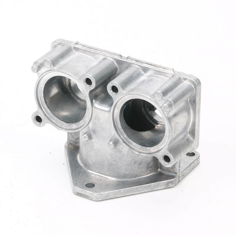 Die casting powers automotive innovation when one controlled casting can reduce system mass or assembly complexity, manage heat or electromagnetic functions, and deliver repeat geometry at a total cost that justifies tooling. Those benefits are conditional. The exact alloy, casting route, load path, crash role, porosity risk, joints, corrosion system, machining, validation, APQP, and production controls must support the vehicle function. A lighter raw material or lower part count does not automatically make a safer, more durable vehicle.
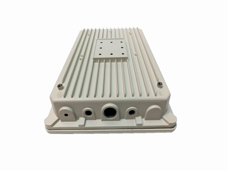
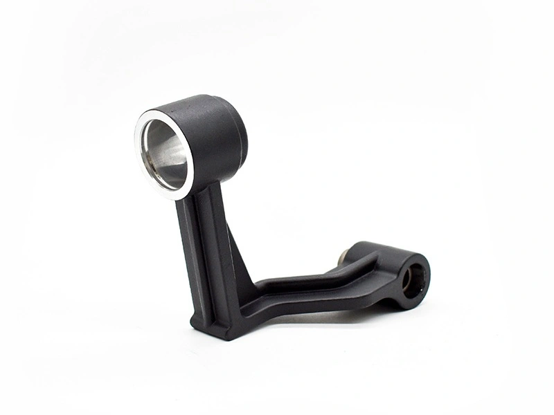
The process is well established for housings, covers, brackets, transmission and driveline cases, thermal hardware, electronics enclosures, handles, controls, and many other components. Large structural castings can also consolidate body assemblies, but their engineering burden is different from that of a small control housing. Product safety classification, crash load paths, repair strategy, joining, dimensional architecture, and material behavior must be approved for each platform.
Start with the vehicle system, not the casting
Define what the component does in the vehicle. State static, fatigue, crash, vibration, impact, pressure, temperature, electrical, thermal, sealing, corrosion, appearance, fire, service, and recycling requirements. Identify interfaces with body structure, battery, motor, inverter, gearbox, cooling circuit, connector, seal, fastener, adhesive, weld, coating, and service tool. Mark special characteristics and product-safety consequences under the customer's system.
Compare complete assemblies. A die casting may replace stampings, welds, brackets, fasteners, sealants, machining fixtures, and inspection stations. It may also require thicker local sections, inserts, heat treatment, machining, impregnation only if permitted, coating, more complex handling, and expensive tool maintenance. Calculate finished mass and total conversion cost, not density multiplied by volume.
Part consolidation changes failure behavior. Removing joints can reduce tolerance accumulation and assembly operations, yet one casting can concentrate many functions and increase the impact of scrap or damage. Determine whether a local defect, tool change, or dimensional drift affects one minor feature or an entire vehicle structure. Design inspection and containment around that consequence.
Choose the casting route with the alloy
Aluminum die casting covers several machine, vacuum, squeeze, semi-solid, and alloy strategies. A380, ADC12/A383, A360, A413, AlSi12, structural HPDC alloys, A356, and AlSi10Mg do not share one route or delivered condition. A material used in gravity, low-pressure, additive, or wrought form cannot be transferred to conventional high-pressure die casting by name alone.
Select exact chemistry and condition from product needs: filling, pressure integrity, strength, ductility, crash energy, fatigue, thermal conductivity, corrosion, machining, joining, coating, dimensional stability, recycled content, and supply. A grade such as A380 is a common HPDC reference, not an automatic automotive approval. Some properties compete. Increasing alloying or heat treatment to improve strength may alter ductility, conductivity, corrosion, distortion, or process feasibility.
Heat treatment requires route-specific evidence. Entrapped gas in conventional HPDC can create blistering or dimensional change during some thermal cycles. Vacuum and process controls may improve feasibility, but geometry and internal integrity still matter. Specify the intended condition and demonstrate it on representative castings rather than attaching a temper from another route.
Use aluminum, zinc, and copper where each earns its place
Aluminum is attractive for housings, thermal structures, motor and inverter cases, transmission components, brackets, and selected body or battery structures where low density and integrated geometry have system value. Zinc can fit compact handles, locks, controls, connector hardware, gears, and decorative or precision components where small detail, surface finishing, and mechanical feel matter more than minimum mass.
Copper-based materials can provide a local current path, heat transfer, wear, or fluid function, but copper alloy and casting-route feasibility must be confirmed. A machined, stamped, forged, or bonded copper conductor may be better than making an entire housing from copper. Hybrid components can combine an aluminum structure with copper busbars, steel inserts, polymer isolation, and selected wear materials.
Every hybrid interface needs retention, preload, galvanic area ratio, sealing, thermal expansion, electrical resistance, heat flow, fatigue, fretting, coating, assembly, and repair review. An insert that shifts, corrodes, loosens, or traps fluid can erase the intended material advantage.
Lightweight by function, not by density
Vehicle energy use and EV range depend on total vehicle mass, duty cycle, aerodynamics, rolling resistance, climate loads, battery, controls, and many other factors. Do not convert a component material change into a universal range or fuel-economy percentage. Measure finished assembly mass and use the OEM's vehicle model to quantify system impact.
Low density is only one input. Stiffness, crash deformation, fatigue, attachment load, casting wall, ribs, local bosses, machining stock, corrosion allowance, inserts, and joining determine final geometry. Compare a feasible aluminum casting against a feasible stamped, extruded, forged, machined, or mixed-material assembly at the same vehicle functions.
Mass should be placed where it works. Integrating ribs near load paths, moving material away from low-value zones, and combining thermal or shielding functions can improve efficiency. Simulation should include casting constraints and real interfaces. Topology output that cannot fill, vent, eject, trim, machine, join, coat, inspect, or repair is not production lightweighting.
Treat structural integration as a safety program
Large body, chassis, subframe, suspension, battery, and crash-related castings require approved load cases, material models, strain-rate behavior, joints, local defects, fatigue, corrosion, crash, durability, manufacturing variation, and repair strategy. The term “structural casting” does not establish suitability. Design authority and OEM requirements control the application.
Material cards and simulation models should reflect the actual alloy, process, heat treatment, section, specimen source, orientation, strain rate, temperature, and manufacturing variation. Separately cast coupons may not represent a gate region, heavy node, thin wall, machined surface, or local oxide film. Correlate simulation with representative components and physical tests.
Define internal-integrity zones around load paths, joints, machining, and crash hinges. Inspection must have sufficient access and resolution for the accepted discontinuity model. NDE cannot guarantee performance by itself. Product validation may include component and assembly fatigue, crash, vibration, environmental, corrosion, and abuse tests according to the authorized plan.
Use die casting for EV thermal and electrical integration
EV motor, inverter, charger, converter, battery, and control hardware often needs heat spreading, coolant containment, electromagnetic shielding, connector location, sealing, and grounding. A casting can integrate fins, channels, mounts, covers, and interfaces. The benefit depends on the complete heat and electrical paths, not nominal bulk alloy conductivity.
For thermal design, define heat sources, transient duty, coolant or airflow, pressure drop, temperatures, boiling or erosion risk, cleanliness, channel geometry, thermal interface material, flatness, joint pressure, and service cycles. Validate production-representative castings with instrumented boundary conditions. A room-temperature leak test does not establish pressure-cycle, thermal-cycle, or cleanliness performance.
For EMI and electrical bonding, define frequency range, openings, seams, fasteners, gasket, coating, grounding pads, oxide, corrosion, and assembly preload. Machining and finish can dominate contact resistance. Shielding effectiveness measured on a simple plate cannot approve an enclosure with connectors, vents, covers, and cable penetrations.
Compare die casting, stamping, forging, and machining
Vehicle need | Route to screen | Evidence before selection |
|---|---|---|
Integrated housing, thermal, shielding, and mounting features | Aluminum die casting | Alloy/route, DFM, integrity, dimensions, thermal/electrical and durability tests |
Large thin sheet structure with flanges and welded assembly | Steel or aluminum stamping | Forming, springback, weld/adhesive, corrosion, crash and tolerance stack |
Highly loaded compact member or shaft | Forging plus machining | Material form, grain flow, heat treatment, fatigue, NDE and load tests |
Low demand, changing design, or controlled stock condition | CNC machining or fabrication | Stock traceability, residual stress, datum plan, cycle and total cost |
Local mixed electrical, wear, sealing, or structural functions | Hybrid casting and inserts | Interface retention, galvanic, thermal, fatigue, assembly and inspection |
The comparison should use production-feasible designs at equal load, environment, mass, life, quality, and demand. Stamping can be efficient for large sheet forms but adds dies, springback control, welding, adhesives, and assemblies. Forging can support demanding load paths but needs preform, heat treatment, machining, and inspection. Machining can reduce tool commitment but adds stock and cycle exposure.
Design gates, vents, vacuum, and machining around function
Use DFM to align parting, gates, runners, overflows, vents, vacuum where used, cooling, slides, ejectors, trim, and machining with the function map. Avoid placing heavy junctions and predicted air traps at seal lands, bearing seats, threaded joints, fatigue concentrations, weld interfaces, grounding pads, and deep machining zones where possible.
Simulation can compare fill and solidification concepts, but trial evidence must correlate the model. Inspect cavity-specific sections and internal regions selected by risk. Track machining breakout, leakage, surface, dimensions, and function. A lower predicted porosity percentage is not a part acceptance criterion unless connected to a validated method and performance limit.
Machining requires stable datums, stock, fixture support, clamping control, cutting access, burr removal, cleanliness, and final inspection. Machining can expose pores and alter corrosion or fatigue surfaces. Mark no-breakout and boundary zones before tool release.
Manage tooling as a production variable
Tool condition changes fill, flash, dimensions, surface, porosity, and ejection. Define material and heat treatment, cooling, gates, vents, vacuum seals, cores, slides, ejectors, trim, replaceable inserts, preventive maintenance, repair, and validation after repair. Coordinate that plan with tool and die engineering. Do not specify a universal tool-life shot count.
End of life may be a worn gate, cracked core, excessive flash, lost texture, slide movement, blocked cooling, dimensional drift, or a repair that no longer supports accepted parts. Trend tool features with casting results by cavity. Parts since maintenance, failure location, and process history are more useful than total cycles alone.
Large castings increase consequence. Tool downtime, insert lead time, machine capacity, spare strategy, crane and handling, trim, scrap recycling, and contingency capacity belong in sourcing review. A low piece quote without continuity and recovery planning can expose vehicle launch or service supply.
Build corrosion protection as an assembly system
Automotive corrosion depends on alloy, casting surface, machining, pretreatment, coating, fasteners, sealants, adhesives, dissimilar metals, area ratio, drainage, stone impact, temperature, road salts, cleaners, fluids, condensation, and electrical potential. No surface treatment is best for every vehicle zone.
Aluminum castings may use conversion coating, anodizing where alloy and appearance permit, paint, powder, e-coat or another qualified post-process system. Zinc parts may use plating and topcoat systems. Mask threads, seal lands, bearing fits, thermal pads, grounding zones, and adhesive interfaces as required. Qualify the actual production substrate and assembled joint, not only flat coupons.
OEM cyclic corrosion tests often combine wet, dry, salt, temperature, and damage conditions. A neutral salt-spray duration cannot be substituted unless the authorized specification allows it. Define acceptance for blistering, creepage, red or white corrosion, adhesion, function, and post-test disassembly.
Separate IATF, APQP, PPAP, and product approval
IATF 16949 is a quality-management-system standard for eligible automotive production and service-parts organizations, used with customer-specific requirements. Certification applies to an audited site and scope, not to an individual casting. ISO/TS 16949 is the predecessor terminology and should not be presented as a current part standard.
APQP is a planning framework used to translate customer requirements into design and process controls. Depending on responsibility, deliverables can include feasibility, flow diagram, DFMEA or design inputs, PFMEA, control plan, measurement analysis, capability plan, tooling, packaging, capacity, and validation. Customer-specific manuals control required methods and approvals.
PPAP is a customer submission and approval process for production parts and changes. Submission level, evidence, significant production run, sample quantity, capability, material and performance results, appearance, tooling, laboratory status, and records depend on customer requirements. A completed package does not excuse nonconforming product or prove indefinite process stability.
Control special characteristics and production evidence
Flow drawing and customer characteristics into PFMEA, control plan, work instructions, tooling, process monitoring, gauges, sampling, records, reaction, and sub-tier requirements. Distinguish product characteristics from process parameters. A shot parameter can support control but cannot replace measurement or function unless correlation and customer approval establish it.
Use measurement-system analysis appropriate to variable or attribute decisions. Establish cavity-specific capability where required and statistically valid. Investigate distributions, tool wear, autocorrelation, measurement uncertainty, and lot patterns rather than reporting a single index without context.
Material and process traceability should support containment. Link alloy lot or melt, cavity, tool revision, machine, process lot, heat treatment, machining, coating, inspection, rework, and shipment as contractually required. Test retrieval before launch. “Full traceability” has value only when a suspect shipment can be reconstructed promptly.
Validate durability in the finished assembly
Choose tests from product duty: static proof, fatigue, vibration, shock, crash, pressure cycling, leak, thermal cycling, coolant or fluid compatibility, corrosion, stone impact, electrical bonding, shielding, thermal performance, ingress, fastener retention, and assembly endurance. Define sample state, cavity, lot, process condition, instrumentation, acceptance, and deviations.
Inspection methods answer separate questions. Chemistry verifies sampled composition. CMM and gauges address dimensions. Radiography or CT can inspect selected internal volumes. Penetrant can support selected surface indications. Leak tests assess a defined boundary. No one method proves strength, fatigue, pressure, corrosion, and dimensional capability together.
After a design, alloy, tool, process, machine, site, heat treatment, machining, coating, inspection, or sub-tier change, evaluate affected evidence. Customer notification, PPAP resubmission, validation, containment, or approval may be required. Tool repair is also a process change when it affects gate, vent, cooling, cavity, or special characteristics.
Move from concept parts to production evidence
Early vehicle programs often use machined billet, fabricated, printed, gravity-cast, or soft-tool parts before production HPDC is available. These samples can answer package, assembly, thermal, hydraulic, connector, software, or selected load questions. Their material condition, joints, surface, porosity, dimensions, and failure behavior may differ from the production casting. Label the route and condition in every design-verification record.
Plan the evidence transition rather than waiting for PPAP. Identify which tests remain valid across routes, which need correlation, and which must be repeated on production-intent alloy, die, cavity, process, machining, coating, and assembly. Use dimensional correlation, material characterization, sectioning, internal inspection, leak and thermal tests, fatigue or crash tests, corrosion, and vehicle builds according to the product risk and customer plan.
Production-intent does not mean merely using a hard tool. Machine, cavity count, melt and return policy, vacuum and cooling, trim, heat treatment, fixtures, cutting tools, special processors, gauges, packaging, rate, maintenance, and operator instructions should represent the submitted process or be declared as open deviations. Approval based on heavily selected or hand-finished samples creates a weak launch baseline.
Send an RFQ that defines the vehicle and approval boundary
Provide controlled drawings and models, vehicle system and failure consequence, loads and environments, exact alloy or approved alternatives, casting route, demand and ramp, special characteristics, product safety status, internal-integrity zones, machining, joining, finish, functional tests, APQP/PPAP level, customer-specific requirements, approved sub-tiers, traceability, record retention, packaging, capacity, change notification, and service-parts horizon.
Ask the supplier for feasibility exceptions, alloy and route, site and current QMS scope where required, DFM, tool and cavity concept, process flow, sub-tier map, integrity controls, measurement and test methods, APQP timing, PPAP responsibility, capacity evidence, maintenance and spares, launch containment, nonconformance authority, continuity, and open risks. Use engineering review before steel release.
Automotive die casting is innovative when it produces a better vehicle system with evidence that survives launch and repeat production. Integration, low density, and high output are possibilities, not conclusions. The defensible decision aligns alloy, route, geometry, interfaces, durability, corrosion, tooling, quality planning, approval, capacity, and change control.
FAQs
What are the advantages of using die casting in electric vehicles?
Which aluminum alloys are most common in automotive die casting?
How does die casting compare to stamping or forging in automotive parts?
What surface treatments are best for corrosion protection in cars?
Can die cast automotive parts meet ISO/TS and PPAP standards?