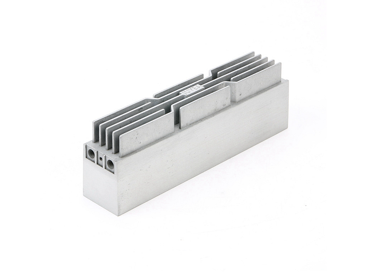
Custom die cast aluminum heat sinks are most effective when they combine heat spreading, fins or pins, mounting, enclosure walls, EMI partitions, sealing, connector supports, and airflow features in one repeatable component. They are strong candidates for LED luminaires, motor drives, power supplies, telecom radios, charging equipment, industrial controls, cameras, and sealed electronics where three-dimensional integration offsets the thermal conductivity and tooling advantages of other routes. They are not automatically the coolest option. The decision must be based on protected-component temperature and performance under actual power, interface, airflow, orientation, ambient, contamination, enclosure, control, and aging conditions.
A heat sink does not "remove" heat by material name. Heat crosses the package, joint, interface material, contact, heat-sink base, spreading region, fins, boundary layer, surrounding air or liquid, and enclosure before reaching the environment. Any one resistance can dominate. A highly conductive alloy cannot repair a dry or unloaded interface; dense fins can increase area while choking airflow; a black surface can change radiation without solving poor conduction or convection.
List every meaningful heat source and its location: semiconductors, LEDs, magnetics, batteries, motors, resistors, processors, radios, displays, and neighboring equipment. Separate steady, burst, startup, charging, overload, fault, standby, and control states. Use credible losses rather than electrical input power where the difference matters. State whether sources operate together and how software, current limiting, fan control, or thermal throttling changes heat with temperature.
Define limits at the right entities: junction or case, PCB, solder joint, magnetics, battery, optical element, adhesive, gasket, lubricant, cable, accessible touch surface, and nearby air. Include performance limits as well as survival. A power module that avoids damage by throttling may still fail its output requirement. Set ambient temperature, altitude or air density, solar load, enclosure recirculation, neighboring heat, installation spacing, and allowed warm-up time.
Specify orientation and use. Natural-convection performance changes when channels rotate or face a wall. Forced air depends on fan curve, filter, grille, duct leakage, bypass, recirculation, fan tolerance, speed control, and failure state. Outdoor products face dust, insects, rain paths, ice, salt, and UV; factory cabinets may accumulate oil mist and fibers. Test the configuration that will actually be installed.
Map junction-to-case, case-to-interface, interface-to-base, base spreading, fin conduction, convection, radiation, and enclosure-to-ambient paths. Add parallel paths through PCB copper, fasteners, cables, chassis, potting, and mounting frame where they are meaningful. State which temperatures and heat flows will validate each model assumption.
The thermal interface often controls early prototypes. Define material, nominal and compressed thickness, conductivity basis, area, flatness, roughness, contact pressure, clamp pattern, pump-out, phase change or cure, contamination, electrical isolation, application process, rework, and aging. Avoid using excess interface material to bridge an uncontrolled gap; bond-line thickness can erase an alloy conductivity advantage.
Heat spreading depends on source footprint relative to the base, base thickness, local pads, hollow regions, ribs, material conductivity, and multiple-source interaction. A thicker base may spread heat but adds mass and conduction length; a thin base can create a hot spot beneath a small source. Use analysis and temperature mapping to place metal where it reduces the dominant resistance.
Aluminum die casting can form radial fins, pin arrays, curved ducts, enclosure walls, bosses, cable routes, mounting feet, gasket flanges, connector openings, ground points, and protective guards. The process can make heat-source location, mounting, airflow, and enclosure geometry relative to one tool, reducing assembly stack and separate brackets.
Extrusion offers a constant cross-section, established wrought alloys, and straightforward length changes. Machining supports low demand, fast revision, local precision, and materials not tied to casting. Skived, bonded, folded, forged, stamped, or cold-plate solutions can deliver taller/thinner fins, different area density, or liquid cooling. Fans, heat pipes, vapor chambers, graphite spreaders, and remote radiators solve other constraints. Compare complete thermal architecture rather than forcing every project into a cast sink.
Die casting becomes less attractive when the design is immature, demand cannot support tooling, the envelope needs very tall parallel fins, bulk conductivity dominates, repeated length variants suit extrusion, or liquid channels require a joining and leak strategy beyond the casting. A hybrid can use a cast enclosure/base with an extruded fin pack, heat pipe, cold plate, or separate spreader.
A380 and ADC12/A383-type alloys are common screening choices for integrated high-pressure cast heat-sink housings because of castability, mechanical behavior, machining, and established production. A360, AlSi12, or dedicated high-conductivity die-casting compositions may fit selected thermal, corrosion, fill, or structural requirements. Exact designation, chemistry, process condition, source, and property basis must accompany any conductivity claim.
Thermal conductivity is temperature- and condition-dependent, and published values may describe different standards, specimen routes, heat treatments, or ideal samples. Confirm whether data represent high-pressure cast material and relevant section. Where system performance depends on conductivity, define test method, specimen relationship to production, sampling, and change control. Do not assign wrought, gravity-cast, or additively manufactured values to a conventional high-pressure casting.
Alloy selection also affects die soldering, flow, shrinkage, porosity/oxide behavior, machinability, corrosion, coating response, strength, creep/relaxation, recycling, availability, and cost. A modest conductivity gain can be lost if difficult filling forces thicker fins, opens pores at machined pads, reduces saleable yield, or requires an unstable supply route.
Fin efficiency falls as a fin becomes longer, thinner, or less conductive; area far from the base may contribute little. Spacing must allow boundary layers and fluid to move. In natural convection, closely spaced fins can merge boundary layers and trap warm air. In forced flow, dense fins raise pressure drop and can shift a fan away from its intended operating point. Pin fins may accept multi-directional flow but create different drag and cleaning behavior.
Define inlet temperature, direction, velocity or fan curve, duct, bypass, recirculation, neighboring boards, grilles, filters, and exhaust. Model system pressure drop, not an isolated heat sink in unlimited flow. Include fan tolerance, speed control, acoustic limits, dust loading, and fan-out condition. A lower fin temperature is not useful if the fan consumes unacceptable power or noise.
Orientation, gravity, radiation view, and enclosure spacing matter in passive systems. Keep natural-convection channels open to incoming cool air and outgoing buoyant flow. Avoid horizontal shelves that pool warm air unless the architecture accounts for them. Surface area hidden against a PCB, wall, label, potting, or close cover may not behave like exposed area in a catalog calculation.
There is no universal minimum fin thickness. Feasibility depends on alloy, fin height and taper, length from gate, spacing, orientation to flow, gate/runner/overflow/vent concept, die temperature, machine and projected area, cavity count, tool steel, draft, ejector access, die filling, cleaning, coating, and acceptable short-fill or distortion rate. A thin fin that appears in one trial may not be stable across startup, cavities, tool age, and alloy lots.
Thermal and casting DFM should run together. Gate and overflow placement can consume areas desired for airflow. Deep narrow tool steel between fins must survive thermal cycling, erosion, cleaning, and ejection. Draft and tip radii affect air area and tool release. Fin bases should transition without a heavy isolated node that shrinks or a sharp notch that cracks.
Fins also face handling, vibration, impact, assembly tools, packaging, and field cleaning. Bent fins alter flow and may create sharp edges or electrical clearance problems. Define allowable fin damage, straightening, inspection, guards, packaging, and repair. For dirty environments, wider accessible channels may retain performance longer than a high-area array that quickly blocks.
Mounting bosses and clamps must create sufficient, durable contact without bending the PCB, package, base, or enclosure. Analyze screw torque, spring or clip load, insert retention, thermal expansion, relaxation, gasket compression, and service cycles. A flat pad in free state can bow after the sink is bolted to a distorted chassis.
Post-machining can establish contact pads, bores, threads, gasket grooves, connector openings, and datums where function requires it. Define stock, fixture restraint, tool path, burrs, cleanliness, residual wall, and inspection. Machining can open subsurface pores at an interface or sealed boundary. Machine the pad only when the resulting contact resistance and assembly control justify the operation.
Measure pad flatness and profile in the state that reaches assembly and, where necessary, after mounting and temperature. Surface roughness alone does not predict contact; waviness, local steps, debris, coating, interface compliance, and clamp distribution also matter. Correlate dimensional results with pressure film, bond-line sections, or thermal measurements as appropriate.
An integrated sink may also be an enclosure, RF shield, ground, ingress boundary, optical frame, or structural mount. Coatings and gaskets change thermal contact and electrical continuity. Slots that improve convection can open EMI or ingress paths. A heavy thermal mass can reduce a short peak while increasing warm-up time or transferring heat to a battery, seal, sensor, or touch surface.
For power electronics, define creepage, clearance, accessible metal, grounding, isolation, fastener length, conductive debris, and fault behavior according to the product architecture. For outdoor or sealed electronics, trace water through joints, machined pores, connectors, vents, membranes, fasteners, and thermal interfaces. The complete configured product carries electrical, ingress, and safety claims, not the casting alone.
Vibration and thermal cycling can relax fasteners, pump interface material, crack solder joints, fret grounds, open seals, or move heavy sinks relative to the PCB. Validate the mounting system before claiming a thermal benefit. Recheck thermal performance after relevant mechanical and environmental aging.
Anodizing can provide an oxide function, appearance, wear, and corrosion behavior on suitable alloys, but high-silicon die castings may show uneven color or process signatures. It does not increase bulk aluminum conductivity and it adds an electrically and thermally resistive layer at contacts. Keep or control finish at interface pads, grounds, threads, seals, and bonds.
A dark, high-emissivity surface can increase radiative heat transfer when surface temperature, surrounding temperature, view factor, area, and wavelength-dependent properties make radiation meaningful. It does not guarantee a lower junction temperature. In many forced-air systems convection dominates; in enclosed passive systems radiation may be more important. Compare the complete coated and bare configurations under the intended boundary conditions.
Conversion plus paint, powder coating, or other qualified systems may protect outdoor sinks, but film buildup can bridge fins, change pressure drop, insulate contact zones, trap in recesses, and alter grounding. Surface preparation may expose pores. Validate adhesion, corrosion, UV, chemicals, thermal cycling, edge damage, masking, and repair on production-intent castings.
Decision | Dominant uncertainty | Useful production-intent evidence |
|---|---|---|
Interface and spreading | Bond line, pressure, flatness, source footprint and conductivity | Contact mapping and temperature field at controlled power |
Natural-convection fins | Orientation, boundary-layer interaction and enclosure recirculation | Configured temperatures across orientations and ambients |
Forced-air fins | Fan operating point, bypass, pressure drop, noise and filter loading | System flow/pressure plus thermal and acoustic maps |
Outdoor or dirty use | Corrosion, coating damage, dust blockage, water and cleaning | Aged/contaminated thermal, ingress and surface inspection |
Integrated enclosure | EMI, grounding, seals, touch and neighboring components | Complete-device thermal, electrical, RF, ingress and safety tests |
Correlation matters more than an attractive simulation. Document geometry revision, mesh, material data, contact assumptions, heat loads, boundary coefficients or fluid model, fan curve, radiation properties, convergence, and result sensitivity. Instrument prototypes with calibrated sensors placed to answer defined questions. Account for sensor attachment, lead conduction, calibration, emissivity settings, and ambient measurement.
Test at minimum, nominal, and worst credible production states where variation matters: interface thickness, clamp load, alloy conductivity, base flatness, fin fill, coating, fan tolerance, dust, orientation, ambient, and source power. Record component performance and controls, not just one heat-sink surface temperature. Use failures to update the model and acceptance plan.
Monitor alloy/source, melt and die thermal state, shot profile, vacuum where used, spray, cooling, cycle interruptions, ejection, trim, cavity, tool repairs, machining, cleaning, finish, and handling. Short fins, cold shuts, oxide films, gas/shrinkage, distortion, soldering, flash, broken tool steel, and coating bridges affect thermal or mechanical function differently. Trend location and cavity rather than pooling all defects.
Inspection should target known failure modes. Dimensional gauges can control fin envelope, pad, mounts, and interfaces; visual or automated checks can find defined short-fill or damage signatures; radiography or sections can support selected critical zones; thermal functional tests can detect some missing-interface or process errors in assembled products. Define sensitivity, sampling, false accept/reject handling, containment, and design authority for deviations.
Require change review for alloy or source, return level, shot window, gate/vent repair, cavity insert, tool cooling, machining program or fixture, finish chemistry, mask, interface material, fastener, fan, enclosure, firmware, or supplier change. Revalidate the thermal questions affected by the change rather than repeating an unrelated generic test.
Machined heat sinks can quickly test envelope, interface, base spreading, mounting, and an approximate fin concept, but billet or plate material and machined surfaces do not reproduce die cast conductivity, draft, fin fill, porosity, residual stress, or tool-limited geometry. Extruded samples can test a constant-section option. Printed polymer models support assembly and air-path visualization but not direct aluminum thermal proof unless the method and material are qualified for that purpose.
Prototype planning should label each question, method, material, configuration, due date, measurement, and limitation. Use production-process samples to release casting integrity, fin capability, machining stock, coating, cavity variation, and serial thermal correlation. A fast mockup is valuable when its evidence boundary is explicit.
Count design, analysis, prototypes, tooling, trim, machining, interface materials, fasteners, fans, finish, inspection, assembly, yield, rework, packaging, energy, noise mitigation, filters, cleaning, replacement, warranty, and recycling. A larger passive sink may remove fan energy and maintenance but add mass and envelope. A compact forced-air design may lower casting cost but consume power and require fan/filter service.
Track saleable yield after final machining, finish, assembly, thermal test, visual inspection, and pack-out. A short fin rejected early has a different cost from a warped interface discovered after coating and assembly. Preserve tooling, programs, gauges, thermal fixtures, approved interface/finish, fan configuration, and spare components for the product service period.
Provide controlled geometry, heat-source map and losses by state, component and touch limits, ambient/altitude/solar conditions, natural or forced flow, fan/duct/filter, orientation, enclosure and neighboring parts, interface and clamp, electrical/EMI/ingress functions, vibration, environment, alloy/route restrictions, machining, finish/masks, dimensions, tests, demand/variants, packaging, service, documentation, traceability, and change rules.
Ask the supplier to return exact alloy/condition and conductivity basis, DFM exceptions, thermal assumptions, gate/vent/overflow/cavity plan, feasible fin geometry and yield risks, tool and maintenance plan, pad/machining/cleaning, finish, samples, inspection and thermal correlation, capacity, timing dependencies, and open decisions. The required output is not "efficient thermal management"; it is a controlled path from each heat source to the stated environment with measured margin in the configured product.