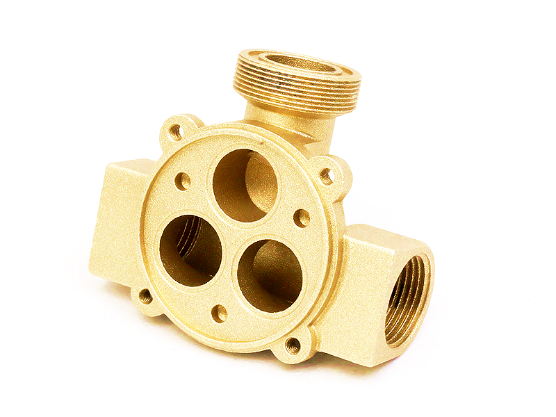
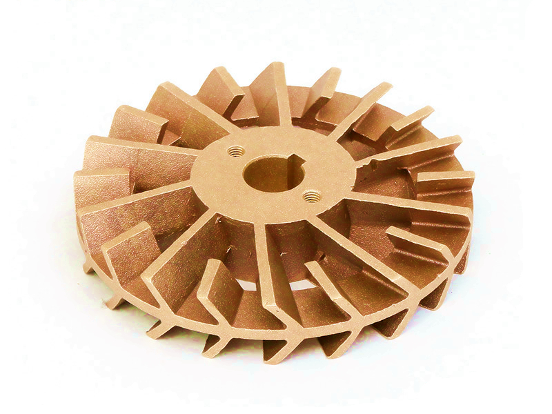
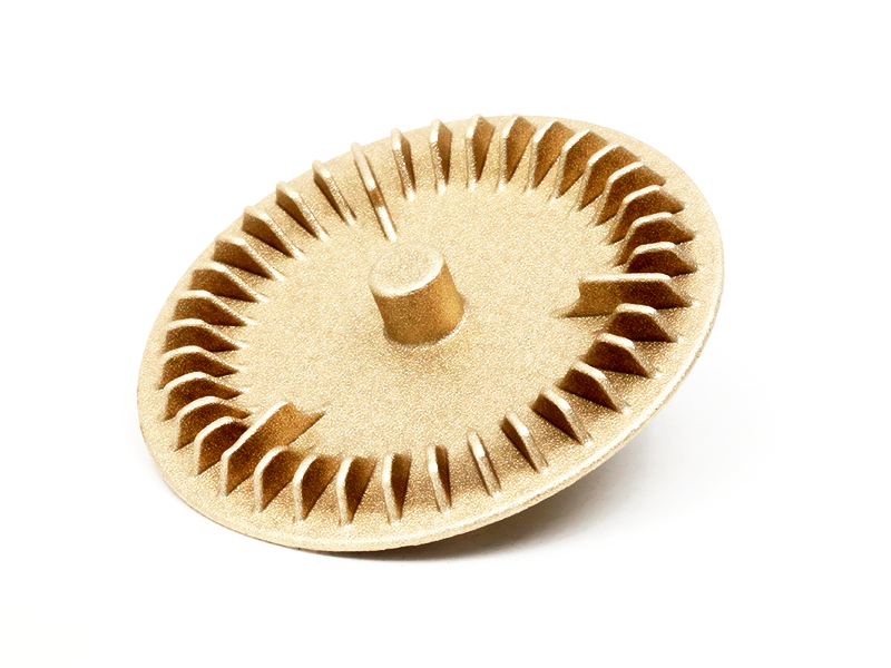
A brass die casting can be a durable pump case, cover, seal carrier, manifold or accessory when the exact alloy is available in the intended casting form and is qualified for the liquid, hydraulic duty and pressure boundary. Brass is not automatically suitable for every water, chemical or HVAC pump. The decision must account for dezincification, stress-corrosion cracking, erosion and cavitation, as well as casting integrity, shaft alignment, seal geometry and external pipe loads.
The buyer should evaluate the finished pump component, not a generic brass property list. A sound proposal identifies which surfaces guide flow, retain pressure, locate the bearing and seal, connect the piping and see the environment. It then assigns the appropriate casting, machining, inspection and pump-level test to each surface. That is the practical basis for sourcing from a brass and copper-alloy casting supplier.
A small hydronic circulator, potable-water booster, chemical dosing pump and seawater transfer pump do not impose the same requirements. Record the pump type, normal operating point, allowable operating range, shutoff condition, speed, start-stop profile and expected pressure pulsation. Define suction conditions because inadequate net positive suction head or inlet restriction can drive cavitation damage that no coating can reliably solve.
Next, define the component. A volute case converts velocity into pressure and controls the impeller discharge field. A seal plate locates the shaft seal and closes the pressure chamber. A bearing bracket carries alignment and mechanical loads. A threaded accessory may sense pressure or drain the case without controlling the main hydraulic path. Their failure consequences and datum schemes differ, so they should not share one generic tolerance or inspection plan.
Feature or zone | Primary function | Main manufacturing risk | Evidence needed |
|---|---|---|---|
Volute, diffuser or flow passage | Guide flow and recover pressure | Core shift, flash, rough transitions or section variation alter the hydraulic area | Traceable section or imaging plus pump curve and efficiency test |
Pressure wall near tongue, ports or plugs | Contain static and cyclic pressure | Shrinkage, entrained gas, machining breakout or local stress | Zone-specific internal-quality evidence, proof and finished leak test |
Seal bore and gland face | Locate and compress the shaft seal | Datum error, runout, surface damage or distortion | Feature-specific dimensional report and assembled leakage check |
Bearing seat and motor register | Keep shaft and impeller aligned | Fixture distortion and accumulated concentricity error | Common-datum measurement and rotating assembly trial |
Inlet, outlet and mounting feet | Connect piping and support the pump | Pipe load, bolt preload and installation strain distort the case | Interface inspection and load-aware structural or assembly test |
This map keeps cost proportional to risk. It also prevents a cosmetic porosity rule from replacing a pressure-zone requirement, or a general dimensional report from missing the shaft-to-seal relationship that controls leakage and wear.
Brass names are often carried across wrought, forged, sand-cast, gravity-cast and pressure-die-cast products without enough qualification. Naval brass and free-machining brass designations may be familiar to pump engineers, but the common tube, plate or bar product does not prove pressure-die-casting availability. Ask for the exact specification, chemistry, product form, feedstock route, delivery condition and applicable material properties.
Cast silicon brass or semi-red brass may be candidates for particular pump cases, but even a cast designation is not automatically suitable for the proposed machine, wall section and fluid. Verify whether the route is pressure die casting, gravity casting or another process, then compare the expected internal quality, tool cost, surface, machining allowance and volume economics. A page for C87850 silicon brass can identify a candidate, not replace the project material review.
Water is not one environment. Obtain pH, temperature, chloride, alkalinity, disinfectant, dissolved oxygen, flow velocity and stagnation information where relevant. For glycol circuits, include concentration, inhibitor package, contamination and maintenance limits. For chemicals, use actual composition and credible upset conditions rather than the phrase light chemicals.
Identify the likely mechanism. Selective zinc removal can weaken a brass pressure wall while leaving a copper-rich surface. Tensile stress from assembly, residual stress or thread loading can combine with a susceptible environment to cause cracking. High local velocity, entrained solids or collapsing vapor bubbles can remove protective films and erode the volute tongue or impeller clearance. Galvanic attack may occur where brass is coupled to aluminum or steel in an electrolyte.
Material selection therefore needs both chemistry and pump hydraulics. A coupon immersion test can compare materials under one fluid condition, but it does not reproduce cavitation, crevice geometry, residual stress or galvanic joints. Qualify the finished case or representative stressed geometry under the mechanisms that matter.
The volute area distribution, tongue geometry, inlet transition and impeller clearance influence head, efficiency, radial load and noise. Casting draft, parting line, cores and machining stock can change those features. The hydraulic designer and tool designer should review the same sectioned model before release. Do not let an unrecorded draft or blend consume the designed flow area.
Choose a parting line that permits stable filling and practical flash removal without placing a trim witness across a critical seal or flow edge. Support cores against shift and define where their position is measured. Keep abrupt thick sections away from the pressure wall where possible. If a passage needs drilling or plugging, show the intersection, burr-removal access, cleaning route and plug qualification on the drawing.
Computational flow analysis can help compare alternatives, but its boundary conditions, surface assumptions and leakage clearances must match the tested pump. A smooth model cannot predict the effect of casting flash or a shifted core unless those conditions are included. Correlate the model with flow, head, power and vibration measurements on production-representative samples.
The pump case cannot be qualified independently from the impeller diameter, blade exit, axial position and intended running clearance. A casting or machining change at the wear surface can shift internal recirculation, axial thrust and efficiency even when the pressure wall remains acceptable. Put the case and rotating geometry under coordinated revision control. The discussion of vane geometry for different pump designs is relevant only when the mating volute and test duty are defined at the same time.
Identify sacrificial wear rings, bushings or replaceable inserts separately from the pressure casting. Their fit, retention and galvanic relationship can control serviceability. If the brass case itself provides a wear surface, define the allowable as-new and service clearances and how they are measured. Do not use a general low-friction claim in place of an abrasion, lubrication and maintenance assessment for the actual liquid.
A brass alloy does not give a pump housing a universal PN rating. Pressure capability follows from material condition, wall geometry, casting quality, threads, plugs, joints, temperature, external loads and duty cycles. Provide normal pressure, shutoff pressure, transients, proof condition, suction vacuum if applicable and abnormal cases. Include piping moments and mounting loads rather than treating ports as unloaded holes.
Mark the pressure boundary and classify zones by consequence. Gate, overflow, vent and local thermal control should be reviewed against those zones. Machining depth matters because a raw casting can be tight before a seal face or bore opens an internal discontinuity. Final leakage screening should therefore follow the last operation capable of creating a leak path.
Proof, burst, fatigue and leak tests are not interchangeable. A leak test detects a through-path at the specified medium and sensitivity. A proof test checks behavior under a stated load without establishing indefinite life. Burst testing measures a failure margin under its procedure, while cyclic testing addresses a defined duty history. The qualification plan should state which question each test answers.
Pump leakage and wear often trace back to relationships among the motor register, bearing seat, shaft axis, seal bore, gland face and impeller chamber. A flange may meet its own flatness requirement while the seal runs eccentric to the shaft. Establish functional datums from the assembled rotating system, then construct the machining setups and measurement plan from those datums.
Machine critical bores and related faces in one restraint condition where practical. Control clamping so a thin case is not measured while distorted and released into a different shape. Specify runout, position, perpendicularity and surface texture only where the seal, bearing or mating component needs them. The post-machining plan should identify casting locators, fixture force, tool access, burr control and inspection after release.
A tapered pipe thread seals through flank interference and sealant behavior. A parallel thread usually retains a fitting while an O-ring, bonded seal or gasket closes the fluid path. A bolted flange depends on face geometry, fastener pattern, stiffness, gasket type and preload. Applying one linear tolerance to all three systems is not technically meaningful.
Name the thread standard, size, class, gauge practice, engagement and sealant assumptions. For flanges, specify the mating standard or custom interface, gasket envelope, face condition, bolt pattern, datum and required assembled test. Protect machined threads and seal lands during blasting, plating, coating and transport. Recheck them after any finish that changes dimensions.
A post-treatment should address a defined exposure. External paint or powder can protect a dry-side case and support identification, but it should normally be masked from gasket lands, grounding points, threads and brazed joints. Metallic plating may improve selected atmospheric, appearance or wear behavior, but porosity, adhesion, thickness distribution and cut edges need qualification. Internal plating adds risks of incomplete coverage, residue and flaking and should not be specified as a generic fix for poor material compatibility.
Flow surfaces require special caution. A coating changes roughness and clearance and may erode near the volute tongue or cavitation zone. It cannot restore unsound base metal. First reduce hydraulic damage through inlet conditions, geometry and operating range, then evaluate a compatible surface system if residual exposure justifies it. Use the supplier's post-process options as process candidates, not as automatic pump approvals.
Question | Representative evidence | Key conditions to record | Boundary of the result |
|---|---|---|---|
Does the case contain the liquid? | Finished-part leak and proof tests | Medium, pressure, temperature, dwell, sensitivity and fixture | Does not establish hydraulic efficiency or unlimited fatigue life |
Does the pump meet its duty? | Head-flow, power and efficiency measurements | Speed, liquid, temperature, inlet condition and impeller revision | Applies to the tested assembly and operating map |
Are rotating interfaces aligned? | Datum-based dimensions, runout, vibration and seal leakage | Assembly preload, temperature and bearing/seal configuration | Individual feature checks do not replace assembly correlation |
Are internal pressure zones sound? | Sections or suitable imaging tied to critical zones | Part orientation, method resolution, cavity and process condition | One view or sample does not prove every future lot |
Will material and finish resist service? | Mechanism-specific fluid, stress, erosion or environmental test | Chemistry, flow, temperature, stress, duration and acceptance | Accelerated exposure is not an unconditional year rating |
Test reports should identify the casting heat or lot, cavity, process condition, machining revision, finish batch and assembly components. An overview of available testing equipment is useful only after the project defines method sensitivity and acceptance. Select methods by the defect or functional question they can resolve.
During tool trials, retain traceability among process settings, dimensional results, internal-quality evidence, leak tests and hydraulic tests. If a section shows that a local wall depends on core position, establish a core-position or process control that can be monitored without cutting every part. If machining exposes porosity at a port, revise the gate, local stock or acceptance zone rather than relying on sealant without approval.
Production controls should cover material identity, melt and die condition, cavity, core/slide position, trimming, machining datums, cleanliness, finish and final leak screening as required. Periodic destructive audits can verify relationships that routine inspection cannot see. Tool repair, gate change, new material source, deeper machining, coating change or plug redesign should trigger a defined requalification review.
A low raw casting price can hide poor yield at machined pressure zones, extensive leak sorting or unstable hydraulic performance. Compare alloy and conversion cost together with tooling, cores or slides, machining, gauges, cleaning, coating, qualification, routine tests, scrap and warranty consequence. Integration is valuable only when it removes joints or operations without creating an uninspectable pressure or flow feature.
Volume changes the answer. CNC machining or another casting route may make sense for development and low demand. Dedicated die casting can become economical when stable geometry and demand justify tooling and process development. Before moving to mass production, confirm that prototype evidence used a representative material, hydraulic geometry, machining route and pressure boundary.
Send revision-controlled 3D and drawings with the volute or passage map, pressure boundary, critical zones, shaft and seal datums, bearing seats, impeller clearance, machined surfaces, threads, flanges, plugs, finish and cleanliness areas. State the exact alloy specification, product form and route or allow documented alternatives. Provide annual volume, lot size, program duration and prototype purpose.
Include liquid composition and concentration, temperature, solids, dissolved gases, disinfectants or inhibitors, flow range, speed, normal and shutoff pressure, transients, suction conditions, starts and cycles, external piping loads, mating materials and applicable product requirements. Define dimensional reports, internal-quality evidence, leak/proof tests, pump curve points, vibration/noise, environmental testing, traceability and change notification.
Ask suppliers to list assumptions and exclusions. The quotation should distinguish raw casting, machined case, coated part and assembled/tested component. It should identify which pump-level tests are included and who supplies the impeller, seal, bearings and motor used for correlation. That clarity makes dates and prices comparable.
Provide drain and vent paths that work in the installed orientation. Avoid pockets where test water, cleaning solution or process liquid remains against a plug or dissimilar-metal joint. Define how chips and media are removed after drilling, threading and deburring. A cleanliness result should name the extraction method and acceptance, because a visually clean volute can still carry particles that damage a seal or block a small circulation path.
Service access also affects durability. Make seals, plugs and wear parts replaceable without loading a thin pressure wall or damaging a coated face. Record casting cavity and material traceability in a location that remains readable after machining and finish. When a returned pump is investigated, that record allows leakage, erosion or alignment evidence to be connected to the actual tool and process history rather than treated as an unexplained material failure.
Choose brass die casting for a pump case or accessory when the verified cast alloy resists the defined fluid, the hydraulic geometry can be produced and inspected, and the completed pressure and rotating interfaces pass the agreed tests. Do not approve the route from a naval-brass label, a universal pressure number or a coating promise.
A durable pump component results from four aligned decisions: material and route, hydraulic and structural geometry, datum-controlled finishing, and qualification on the finished pump assembly. When those records remain linked through production, brass can provide a compact and machinable solution without asking the material name to carry risks that belong to design and process control.
What brass alloys are best for pump housings exposed to water and chemicals?
How accurate are thread and flange tolerances in die cast brass fittings?
Can brass die castings be used in high-pressure HVAC or circulation pumps?
What post-treatments improve brass corrosion resistance for pump enclosures?
What is the lead time for tooling and production of custom brass pump parts?