English

Custom Die Cast Zamak Components for Reliable Medical Device Housings
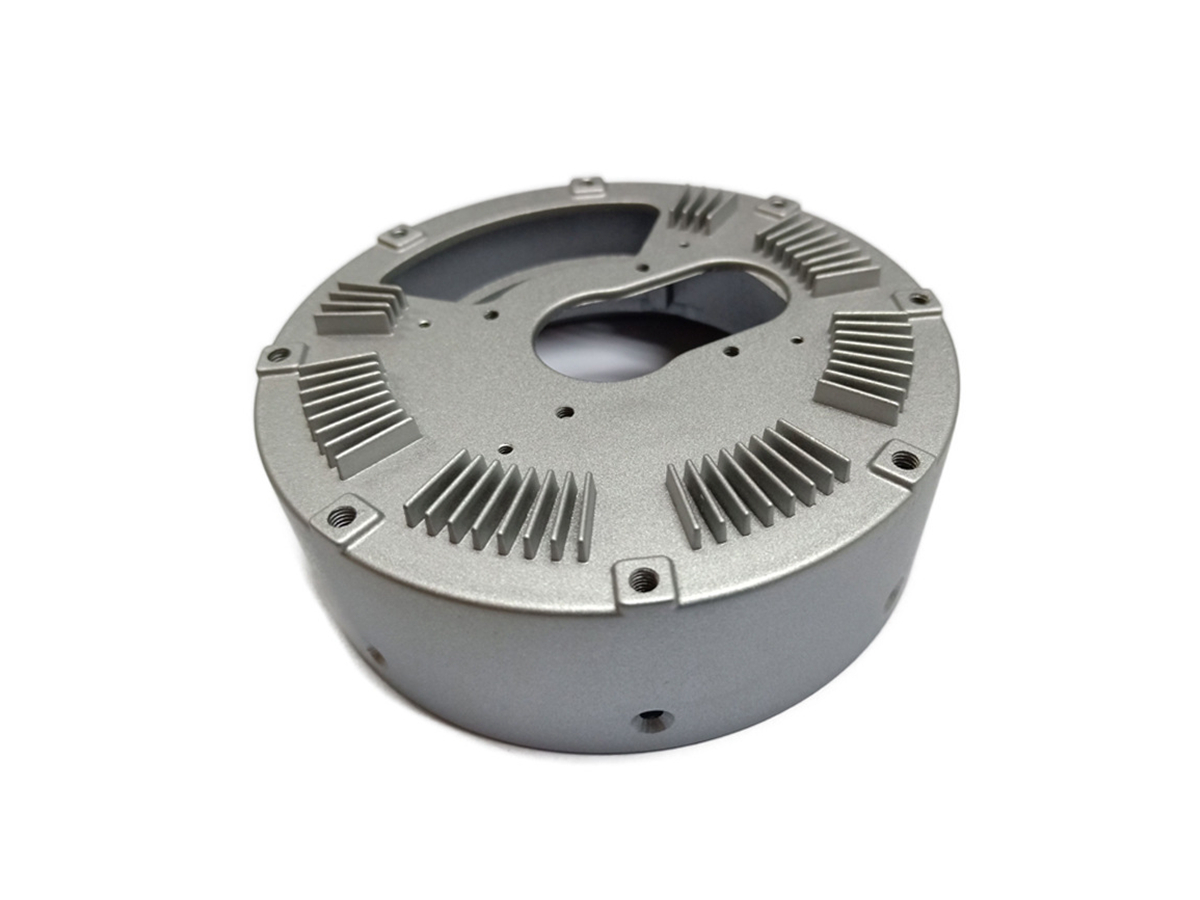
Table of Contents
Define the housing boundary before selecting Zamak
Use a device-level material decision
Select the alloy from load, process, and surface needs
Design ergonomics around the user and the cleaning process
Coordinate parting, gates, ejection, and visible surfaces
Engineer seams, gaskets, and ingress as a system
Preserve EMI and grounding paths through finishing
Control thermal, electrical, and battery boundaries
Qualify cleaning, disinfection, and sterilization separately
Specify surface finishing as a controlled system
Plan machining, inserts, and assembly before tooling
Validate the production-intent housing in the device
Build traceability and change control into the supply chain
Move from prototype to repeat production with defined gates
Prepare a medical housing RFQ that can be engineered
FAQs

Custom Zamak die-cast medical device housing reviewed for ergonomics, sealing, EMI grounding, cleaning, finishing, assembly and traceability

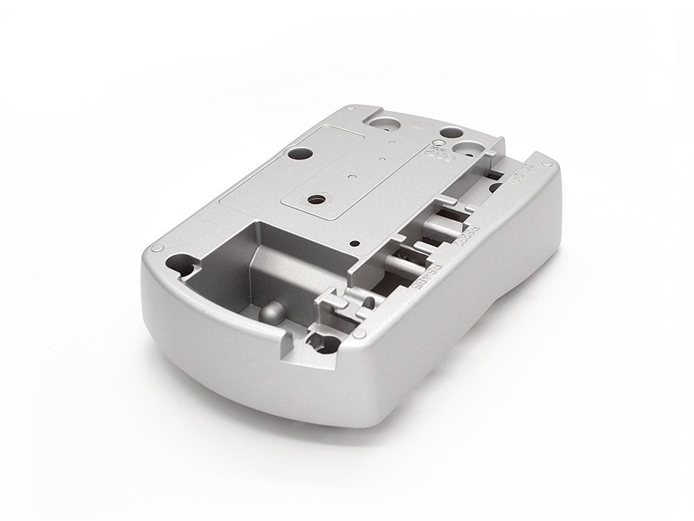
Custom Zamak die castings can suit non-implant medical device housings, internal frames, control bodies, brackets, latches and counterweighted bases when compact geometry, stiffness, integrated features, electromagnetic continuity and production volume justify a metal die. Suitability is not established by calling the alloy medical grade. The device OEM must connect the exact alloy, surface system and manufacturing route to intended use, patient and operator contact, cleaning or sterilization, electrical and mechanical hazards, service life and regulatory evidence.

Zamak should be challenged early when the part enters a sterile field, touches tissue or a fluid path, sees repeated high-temperature moist processing, must be exceptionally light, or depends on an uncoated corrosion-resistant surface. Stainless steel, aluminum, engineering polymer or a multi-material architecture may fit those conditions better. The right decision is made at device subsystem level, not from a material brochure.

Define the housing boundary before selecting Zamak

Identify whether the casting is an external enclosure, internal chassis, handheld grip body, tabletop base, actuator carrier, display frame, battery door, latch, connector bracket or shielding cover. Mark patient, operator, service-technician and environmental contact. State whether the component is reusable, single-use, cleaned between patients, sterilized, covered by a disposable barrier or never exposed during normal use.

Map what the housing protects: electronics, optics, pumps, sensors, batteries, software controls or a mechanical drive. Define the harm if it cracks, opens, corrodes, sheds a coating, loses grounding, traps contamination, misaligns a control or allows liquid ingress. This turns a vague request for reliability into verifiable housing functions.

Zinc die casting for medical housings should be considered only after these boundaries are visible on the drawing and risk file. A non-patient-contact internal frame has different evidence needs from a frequently wiped handheld shell.

Use a device-level material decision

Housing condition

Possible Zamak value

Evidence before release

Compact external or internal enclosure

Integrated bosses, ribs, seats and substantial local stiffness

Drop, impact, fastener and worst-case assembly verification

Handheld control body

Deliberate balance, tactile mass and detailed control geometry

Use study, fatigue/comfort assessment, glove and cleaning evaluation

Electronics shielding shell

Conductive metal path and integrated grounding features

Complete-device emissions/immunity test with final seams and coatings

Frequently disinfected surface

Durable substrate under a qualified finish

Actual chemical, dwell, wipe, dry and service-cycle validation

Sterile-field or repeated sterilization part

Conditional only; method and architecture dominate

Validated sterilization compatibility, residue, corrosion and function

Patient-contact, wetted or implant use

No automatic suitability from Zamak identity

Device-specific material, biological and exposure assessment; alternatives reviewed

The table is a screening tool, not a material approval. For each row, record the applicable device requirement, test method, sample condition and owner. If the required evidence cannot be generated on the production-intent part, change the architecture before tooling.

Select the alloy from load, process, and surface needs

Zamak 3 is often a practical comparison baseline for dimensionally stable, finishable housings. Zamak 5 may be evaluated where loaded lugs, latch features or wear interfaces need a different mechanical balance. Grade selection must follow the controlled material specification, casting geometry, process window, finish and device tests. Do not infer biocompatibility, cleanability or sterilization resistance from the grade number.

Control incoming alloy identity, melt practices, internal returns, contamination and cavity traceability. Porosity that is harmless inside a broad wall may open during machining, compromise a cosmetic surface or create a leakage path. The drawing should distinguish cosmetic, structural, machined, sealed, grounded and hidden regions so process controls match consequence.

Compare Zamak with aluminum, stainless steel, polymer and hybrid structures using finished mass, wall architecture, fasteners, machining, surface protection, shielding, cleaning, tool investment and accepted yield. A denser alloy can still reduce system volume or part count, but it should not be marketed as lightweight without comparing actual CAD masses and center of gravity.

Design ergonomics around the user and the cleaning process

A medical housing can integrate palm contours, finger clearances, trigger guards, control bezels, anti-rotation features and balanced internal mounting. Yet an ergonomic shape is not proven by smooth CAD. Evaluate representative users, tasks, use duration, posture, gloves, hand sizes, impaired dexterity, accidental activation, labeling visibility, cable loads and foreseeable misuse.

Density can provide tabletop stability or counterbalance a display, but it can also increase hand fatigue and drop energy. Locate the center of mass with batteries, boards, motors, cartridges and cables installed. Prototype the complete mass distribution; a hollow printed shell answers shape questions but not weight or inertia.

Grip textures and recesses must remain cleanable. Deep grooves can retain soil or disinfectant, and soft-touch layers may change friction or degrade with use. Use rapid prototypes to compare reach, grip and control layout, then revalidate production-intent cast and finished assemblies.

Coordinate parting, gates, ejection, and visible surfaces

Place gates, overflows, vents, parting, ejectors, slides and trim witness away from gasket lands, touch surfaces, labels, optical paths and high-stress attachment roots. Flash at a handhold can cut gloves or trap contamination. An ejector witness beneath a membrane or label can interfere with adhesion. A slide line through a sealing edge can create an ingress path.

Use ribs and bosses to support load paths without creating abrupt thick-to-thin transitions or inaccessible pockets. Specify cast holes, cored openings and machined features according to function. Threads, bearing bores, connector apertures and gasket surfaces may need machining or inserts; their datum strategy should be defined before tool design.

Review worst-case tool and process conditions, not only nominal CAD. Flow joins, local porosity, distortion, die mismatch and ejection stress can affect a latch or fastener boss. Tool corrections should be tied to measured housing function and cavity identity.

Engineer seams, gaskets, and ingress as a system

A die-cast wall does not by itself create a sealed device. Protection depends on enclosure joints, flatness, gasket compression, fastener pattern, inserts, connector seals, vents, membranes, doors, cable entries and assembly controls. Define the target environment and ingress test for the complete configuration.

Allocate dimensional variation across both housing halves, gasket, coating, inserts and fasteners. Coating buildup on a land can alter compression; masking can create an edge step; porosity opened by machining can connect to the interior. Tolerance and coating stack review should precede tool release.

Verify sealing after drop, fastener cycling, cleaning exposure, thermal conditioning and any other event that can change the joint. A housing that passes an initial ingress test may fail after a corner dents, a gasket takes set or a coated thread loses clamp load.

Preserve EMI and grounding paths through finishing

A conductive Zamak shell can support electromagnetic shielding, but apertures, seams, displays, cables, vents and coatings determine device performance. Identify chassis and protective-earth interfaces, board grounding points, contact pressure, corrosion couples and the current path under fault or interference conditions.

Paint, powder or clear layers can insulate a grounding feature. Define masks, conductive finishes, serrations, washers or machined contact lands and protect them from corrosion. Verify resistance after assembly, vibration, cleaning and service operations. Do not assume a bare boss remains bare through every supplier and repair route.

EMI shielding in zinc housings must be tested on the complete production-intent device with actual boards, cables, firmware, seams, gaskets and finishes. A material conductivity statement cannot substitute for emissions and immunity evidence.

Control thermal, electrical, and battery boundaries

Map heat from processors, power electronics, motors, pumps, chargers and batteries through internal mounts, interfaces and external touch surfaces. Zamak can spread local heat through a compact chassis, but geometry, contact resistance, coatings, air gaps and ventilation control the result. Verify normal use, charging, blocked ventilation and fault conditions defined by the device risk process.

Keep accessible temperatures, clearances, insulation, protective earth and leakage paths within the device requirements. Conductive housings can create useful grounding and shielding paths, yet they can also bridge an unintended electrical fault if insulation, fastener length or wire routing changes. Identify insulating films, bushings, spacers and protected cable edges in the assembly specification.

Battery swelling, venting, replacement and service access deserve explicit space and containment review. A rigid casting should not press a damaged cell or direct a release toward the user. Confirm that drop deformation, loose hardware or a misassembled cover cannot contact energized parts. These are complete-device decisions; the casting supplier should return dimensional and material evidence for the assigned interfaces.

Qualify cleaning, disinfection, and sterilization separately

Cleaning removes soil, disinfection reduces specified microorganisms, and sterilization is a validated process with different requirements. Do not use the terms interchangeably. Obtain the OEM's exact agents, concentrations, water quality, temperature, dwell, wipe force, drying, cycle count and storage conditions. Include misuse that is reasonably foreseeable in the intended setting.

Repeated processing can attack coating pores, sharp edges, rack marks, machined openings, fastener seats and dissimilar-metal joints. It can change color, adhesion, corrosion, grounding, labels, gasket compression and actuator force. Test complete assemblies after the defined processing sequence and inspect both appearance and function.

For steam, low-temperature chemical or radiation processes, review the entire material and assembly set rather than Zamak alone. Coatings, adhesives, labels, polymers, batteries, lubricants and sealed volumes may govern. When the exposure is severe or poorly defined, isolate the casting behind a validated barrier, redesign for a different material or keep it outside the processed zone.

Specify surface finishing as a controlled system

A medical housing finish may need color and gloss control, corrosion protection, cleanability, low particle generation, label adhesion, electrical masking and resistance to specified chemicals. State the complete pretreatment, underlayers, top layer, measurement locations, cure, allowable repair, rack witness and packaging. Avoid unsupported phrases such as medical-grade coating.

Validate cast surface preparation because polishing or blasting can open pores, round sealing edges and alter dimensions. Coating may bridge small gaps, build at edges or remain thin in recesses. Inspect A-surfaces and high-touch zones separately from hidden interiors. A finish that looks acceptable can still fail grounding or gasket fit.

Define what happens after a scratch or chip. If base metal exposure creates an unacceptable corrosion, cleaning or particle risk, the design needs protection, detection or replacement criteria. Rework by stripping and refinishing may change substrate and dimensions; identify reworked parts and repeat affected tests.

Plan machining, inserts, and assembly before tooling

Use machining where the functional requirement justifies it: precision connector openings, bearing seats, sealing lands, datums or threaded interfaces. Provide stock allowance, datum transfer, burr control, cleaning and porosity response. Do not machine every feature merely to make inspection familiar; uncontrolled datum chains can increase variation.

Threaded inserts, self-tapping screws, press fits, adhesives and weld-like joining methods each create different load, contamination and service risks. Verify torque, pull-out, repeated access, galvanic compatibility and debris. Fastener length and insertion depth should not threaten boards, batteries or fluid barriers.

Assembly control should include correct component revision, torque or displacement monitoring where justified, gasket presence, grounding hardware, cleanliness, labels and functional checks. Error-proof similar left/right or language variants and maintain traceability to critical subcomponents.

Validate the production-intent housing in the device

Start with risk-based requirements, then connect each to a method, acceptance criterion, sample condition and record. Potential checks include dimensions, fastener retention, latch cycles, drop and impact, vibration, sealing, cleaning or sterilization exposure, corrosion, coating adhesion, particle or residue concerns, grounding, electromagnetic compatibility, temperature, labeling and service operations. The OEM determines which apply.

Use worst-case production-intent parts: cavity extremes, material lots, maximum and minimum coating, repaired parts if permitted, aged gaskets, repeated fastener access and tolerance-stack assemblies. Test failures should be traced to design, casting, machining, finish, assembly or test setup instead of being hidden by selective samples.

Functional testing for zinc assemblies should confirm the housing's device-level functions after relevant conditioning. Passing raw-casting dimensions is only an intermediate control.

Build traceability and change control into the supply chain

Define lot and cavity identity across alloy, casting, heat or aging interval where relevant, machining, surface preparation, coating load, assembly and final inspection. Retain material and process records according to the OEM's quality plan. Traceability depth should reflect risk and containment needs, not a generic certificate package.

Qualify sub-tier finishers, machinists, insert vendors and assemblers for the controlled specification. Require notification before changes to alloy source, return-metal practice, tool cavity, process location, machining program, cleaner, coating chemistry, cure, mask, repair, gasket, fastener, adhesive, test method or packaging.

Material traceability for zinc castings is useful only when records can isolate affected product and support investigation. A certificate without part, lot and process linkage does not control a medical housing change.

Define record content and retention before sourcing. The supplier's file may need released drawings, inspection results, material identity, process approvals, nonconformance disposition and shipment linkage. The OEM should state which records require review before release, which can be retained by the supplier and how electronic revisions are controlled. More paperwork is not automatically better; every retained record should support product release, traceability, investigation or change assessment.

Move from prototype to repeat production with defined gates

Prototype stages should answer named questions: ergonomic models for reach and balance, machined or printed shells for assembly, finish plaques for color, and production-intent castings for flow, ejection, dimensions and surface. Document what each model cannot prove.

At tool trials, inspect every cavity before mixing parts. Complete machining, finish and assembly on representative pieces, then run the defined device checks. Pilot production should challenge inspection capacity, process capability, cleanliness, packaging and record flow as well as part geometry.

Before repeat orders, freeze the drawing, alloy, tool revision, approved samples, process flow, control plan, inspection methods, sub-tiers, packaging and change rules. Prototype-to-production planning prevents an attractive engineering sample from becoming an uncontrolled commercial process.

Prepare a medical housing RFQ that can be engineered

Provide released CAD and drawings, device and housing function, contact classification, use environment, reusable or single-use status, cleaning/disinfection/sterilization instructions, loads, drop and vibration, seams and ingress, EMI/grounding, thermal and electrical interfaces, controls and labels, target mass and center of gravity, alloy restrictions, finish, dimensions, assembly BOM, cleanliness, inspection, validation, traceability, packaging, volumes and change-control expectations.

Ask the supplier to return alloy and metal-control assumptions, DFM, parting/gate/vent/ejection plan, tool and cavity concept, porosity-sensitive zones, machining datums, finish stack and masks, sub-tiers, assembly controls, validation support, exceptions and dated approval gates. Compare quotations using accepted finished housing cost and evidence, not casting price alone.

Keep responsibility explicit. The casting supplier controls the agreed component processes and records; the device legal manufacturer determines intended use, risk acceptability, regulatory strategy and final device release. Test support from a supplier is valuable only when the OEM has approved the method, acceptance and sample configuration. This boundary prevents a component certificate from being mistaken for authorization of the medical device.

A reliable Zamak medical device housing is therefore a controlled subsystem, not an FDA-approved material claim. Release it when production-intent parts demonstrate the assigned mechanical, ergonomic, environmental, electrical, cleaning and assembly functions in the complete device, with traceable records and controlled changes.

FAQs

  1. Can Zamak die-cast housings be customized for medical ergonomic needs?

  2. How does Zamak handle repeated medical sterilization cycles?

  3. Minimum order quantity for custom Zamak medical components?

  4. Zamak vs. stainless steel: weight benefits in medical devices?

  5. Case studies of Zamak in FDA-approved medical housings?

Copyright © 2026 Diecast Precision Works Ltd.All Rights Reserved.