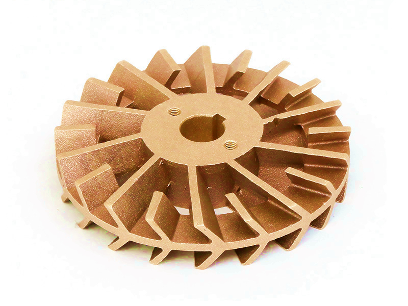
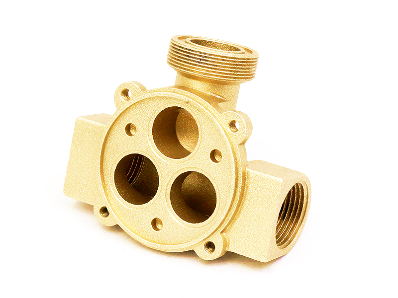
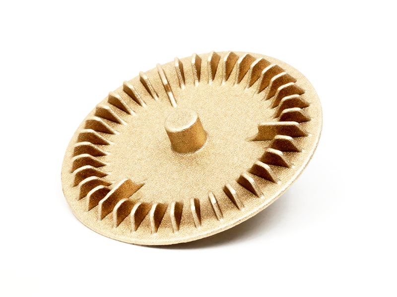
A copper-alloy cast impeller can be reliable when its alloy is available in the intended casting product form and the finished rotor meets the pump's hydraulic, corrosion, strength, runout and balance requirements. The route is most convincing for an open or semi-open impeller, impeller blank, hub, diffuser or wear component whose geometry can be filled, ejected and inspected. It is not justified by copper conductivity or corrosion reputation alone.
The release decision must connect liquid chemistry and solids to vane geometry, cavitation margin, torque transfer, casting quality, final machining and pump-curve evidence. A dimensionally acceptable impeller can still deliver the wrong head, consume excess power, recirculate at the wear clearance or vibrate because mass and hydraulic forces are uneven. Buyers should source the finished rotating system, not an isolated casting.
Provide pump type, required flow-head range, speed range, fluid density and viscosity, temperature, vapor pressure, dissolved gas, solids and expected operating region. Include suction pressure, inlet losses and site conditions used to establish net positive suction head available. A design that works near best efficiency point may recirculate, cavitate or overload the driver at another point on the system curve.
State whether the pump is centrifugal radial-flow, mixed-flow, axial-flow, regenerative, peripheral or another architecture. Open, semi-open and closed impellers have different clearance, casting and inspection issues. A multistage rotor must also match diffusers and adjacent stages. Do not apply a general copper impeller recommendation across these configurations.
The impeller adds energy to the fluid; a diffuser converts velocity and controls stage flow; wear rings restrict recirculation; balance holes, back vanes or balance disks influence axial thrust; the hub transfers torque and locates the rotor. These parts may share material or tooling discussions, but their functional limits differ. A wear ring clearance is not an impeller balance tolerance, and a diffuser passage is not qualified by rotor overspeed evidence.
List every accessory and mating feature in the assembly. Include shaft, key, spline, nut, sleeve, seal, casing, wear ring and diffuser. Mark rotation direction and assembly orientation. A reverse-installed or wrong-hand impeller can look correct during incoming inspection and fail the hydraulic test immediately.
Impeller concept | Route worth comparing | Main manufacturing risk | Approval evidence |
|---|---|---|---|
Open impeller with accessible vanes | Near-net casting with hub/face machining | Vane fill, edge flash, distortion and blade-to-blade variation | Passage scan/sections, balance and pump curve |
Semi-open impeller | Cast route with controlled shroud face and running clearance | Vane-shroud junction quality and axial clearance stack | Face/runout data and assembled clearance/performance test |
Closed impeller with enclosed curved passages | Qualified core/soluble-core, joined construction or alternative casting route | Core removal, passage shift, internal flash and cleanliness | Internal inspection, flow check, balance and hydraulic qualification |
Large marine or slurry impeller | Sand/investment/other casting route comparison | Pressure die casting may not fit size, alloy or section needs | Route-specific material and erosion/cavitation evidence |
Machined prototype rotor | Stock or additive route for hydraulic iteration | Does not reproduce casting porosity, shrinkage or production balance | Explicit risk-closure matrix and later production-intent sample |
A copper-alloy casting route should survive this screen before detailed tooling. Long enclosed channels, reverse curvature, inaccessible flash or a product designation unavailable in pressure-cast form may point to another method. Keep the hydraulic geometry stable while comparing routes so manufacturing convenience does not silently change pump performance.
Copper alloys used in pumps include brasses, bronzes, aluminum bronzes, silicon bronzes and copper-nickel families, but not every familiar impeller alloy belongs in every casting process. C18200 and C17500 are often discussed through wrought or heat-treated property data; those values do not establish a pressure-die-cast impeller route. C95800 and similar aluminum-bronze designations also require exact specification and casting method, not a generic family reference.
Request alloy designation, governing material standard, chemistry, feedstock, casting route and delivered condition. State any heat treatment, joining, machining or coating that follows. Use strength, fatigue, corrosion and cavitation data for the relevant product form and final condition. A chemistry certificate does not prove internal quality or impeller endurance.
Water is not one environment. Chloride, free chlorine or other oxidant, pH, temperature, dissolved oxygen, sulfide, ammonia, conductivity, solids, velocity and shutdown deposits alter corrosion. Glycol systems add inhibitor condition and contamination. Seawater service adds biofouling, galvanic coupling and high chloride. Potable-water scope adds material and regulatory constraints.
Distinguish uniform corrosion, pitting, dezincification, selective phase attack, erosion-corrosion, cavitation erosion and galvanic attack. A grade resistant to quiet immersion may lose material at a vane leading edge or wear-ring gap. Test representative cast, machined and finished surfaces in the actual moving fluid where consequence warrants it.
The inlet eye, hub contour, leading-edge angle and passage area determine incidence and local pressure. Poor entry alignment raises loss and can trigger cavitation. The exit diameter, width, blade angle, slip and volute/diffuser interaction influence head and power. Vane count changes blockage, loading and pulsation; it is not chosen from a standard range without the pump model.
Use one-dimensional sizing to define a plausible baseline, then apply CFD through a controlled engineering workflow where complexity and consequence justify it. Review more than a single design point. Inspect low-flow recirculation, best-efficiency operation, high-flow loading, vapor regions, velocity gradients and unsteady interaction with the tongue or diffuser. CFD assumptions, turbulence/cavitation model, surface condition and boundary inputs should be recorded so test differences can be diagnosed.
Manufacturing needs draft, fillets, uniform sections, gates, vents, overflows and ejection. Each can alter the hydraulic surface. Treat changes to leading/trailing edge, throat area, outlet width, shroud contour or blade thickness as hydraulic changes, not cosmetic DFM. The pump owner should approve them against the model and test plan.
Gate and overflow removal must not leave a projection in the passage. Ejector marks should avoid working surfaces and balance-sensitive regions. For enclosed passages, define how cores are located and removed and how residue or internal flash is detected. Tooling under die-making control needs passage-specific inspection access from the start.
Torque may pass through a key, spline, taper, interference fit, thread, nut or pin. Trace normal torque, start, reverse, jam and overspeed loads through the hub. Check keyway bearing, hub splitting, fillet stress and material removed by bore machining. A thick hub can also become a casting hot spot or conceal internal defects that later open during machining.
Define the functional axis from the final bore or shaft seat and relate vane OD, shroud faces and balance correction to it. Plan machining setups so the bore, locating face and wear-clearance surfaces share a coherent coordinate system. Available post-machining does not by itself establish runout; the datum and fixture chain does.
Wear-ring, tip and axial face clearances affect recirculation, rubbing and efficiency. Their acceptable values depend on diameter, pump architecture, speed, thermal expansion, shaft/bearing deflection, particles and assembly stack. A tight room-temperature clearance can close under operation; a generous clearance can consume head and efficiency.
Allocate clearance among casing, wear ring, impeller, shaft, bearing and assembly datums. Include coating thickness and corrosion allowance. Measure the completed assembly or use a verified stack, then correlate clearance with the pump curve. Do not promise a universal vane or hub tolerance without this system.
Cavitation begins with local pressure and vapor conditions, then causes noise, vibration and surface damage when bubbles collapse. Erosion from solids is a different mechanism, though both can attack leading edges or shroud regions. Improve suction conditions and hydraulic incidence before relying on a harder alloy or coating. Material resistance cannot compensate for a pump operated outside its allowed suction envelope.
Define net positive suction head testing, liquid temperature, gas content, speed and criterion. If cavitation erosion is a life risk, inspect mapped locations after a representative test and compare mass/profile loss or damage progression using an agreed method. A generic cavitation-resistant label is not a life prediction.
A total porosity percentage is rarely a useful impeller acceptance rule. Location, size, morphology and relation to the hub, blade root or machined surface matter. Porosity near a balance correction zone differs from shrinkage at a highly stressed blade-hub junction. Define critical zones from structural, fatigue and machining analysis.
Use radiography, computed tomography, sections, penetrant inspection or other methods according to material, thickness and resolution. Imaging has detection limits. Correlate indications with mechanical or overspeed tests where failure consequence requires it. Ask available inspection equipment to answer a defined defect question rather than promising universal detection.
Static and dynamic unbalance depend on impeller geometry, speed and support. Casting variation, gates, blade thickness, machining, keyways and coatings can shift the mass center. Balance the finished rotor in the defined assembly condition, including keys or sleeves according to the balancing convention. Record correction location and maximum removable material.
Mechanical balance cannot fix hydraulic asymmetry from unequal passages or vane geometry. A rotor may pass a balancing machine yet produce vibration in the pump because pressure forces differ blade to blade or interact with the volute tongue. Use dimensional/passage evidence, rotor balance and pump vibration together.
When the liquid carries sand, fibers, scale or process debris, define particle-size distribution, concentration, hardness, shape and upset load. A nominal maximum particle size is not enough: long fibers can wrap around the eye or hub, while a smaller hard particle can abrade a wear-ring gap. Passage width, leading-edge shape, vane count and open versus closed construction determine whether solids pass, recirculate or lodge.
Compare hydraulic efficiency with clogging and erosion risk. A narrow smooth passage may perform well in clean water and fail in wastewater. A wider open impeller may pass solids but require a different clearance and efficiency expectation. Material and coating tests should include representative particles and velocity where erosion matters; static corrosion coupons do not answer solids service.
Manufacturing debris is a separate threat. Core residue, trim fragments, machining chips, polishing media and coating flakes can damage seals or become imbalance after installation. Define washing, flushing, drying and inspection for enclosed channels. If cleanliness is measured, specify particle collection, size/count or residue method and the surfaces included. Packaging should preserve the approved condition through transport and assembly.
Surface treatment begins with base-alloy compatibility and the damage mechanism. Nickel, organic barriers or sealers may be candidates in some fluids, but they introduce pretreatment, thickness, edge coverage, adhesion and repair questions. Powder coating intended for external static hardware is not automatically appropriate for submerged high-speed vanes. A detached coating can unbalance the rotor or damage downstream components.
Preserve inlet edges, vane profiles, wear clearances and bore fit through coating and masking. Test the finished impeller in flowing chlorinated or saline liquid, including shutdown and restart if relevant. Salt spray may screen coating quality but does not reproduce immersion chemistry, velocity, cavitation or galvanic area ratio.
Characteristic | Why it matters | Verification direction | Decision supported |
|---|---|---|---|
Inlet eye and leading edge | Sets incidence and cavitation behavior | Scan/CMM/template tied to controlled CAD | Hydraulic sample is geometrically representative |
Passage throat and outlet width | Controls blockage, flow and head | Accessible scan, gauges, sections or flow proxy | Blade-to-blade variation is understood |
Bore-to-vane/runout relationship | Affects clearances and mechanical rotation | Measurement from final functional axis | Assembly and balance data are meaningful |
Finished mass distribution | Influences vibration and bearing load | Specified balance method and mounting condition | Rotor is ready for the defined speed test |
Wetted surface/finish | Changes friction, corrosion and debris risk | Visual/topography/coating checks by critical zone | Hydraulic and durability result applies to production finish |
Test head, flow, input power and efficiency over the agreed operating range and speed. Record liquid properties, temperature, inlet condition, instrumentation, stabilization and uncertainty. Evaluate vibration, noise, bearing or seal behavior and axial thrust where relevant. A single duty-point result cannot show shutoff behavior, overload or high-flow instability.
Cavitation tests, overspeed tests and endurance answer separate questions. Name the applicable pump test standard or customer procedure, test grade and acceptance. If a prototype uses a substitute route, document which results transfer to production and which must be repeated. The discipline of functional prototype testing prevents a successful curve from hiding material or casting risk.
Trace material lot, melt/process record, tool/cavity, trim, heat treatment, machining setup, balance correction, finish batch and final inspection. Multi-cavity tools need cavity-specific passage, mass and hydraulic correlation until pooling is justified. Keep nonconforming parts from re-entering after balance or coating without defined rework approval.
Monitor trends that predict pump behavior: critical vane dimensions, bore/runout, finished mass, correction amount, coating and test results. Tool and insert maintenance should respond to measured passage or flash drift. Before mass production, demonstrate capacity through machining, washing, inspection, balance and testing, not casting cycle alone.
Define how technicians will identify rotation, impeller revision, material and allowable reuse. Service removal can damage a bore, keyway, thread or coating even when the vanes look acceptable. State replacement criteria for corrosion, cavitation pits, bent edges, wear-ring clearance and balance correction. If an impeller is cleaned and returned to service, approve the chemical and mechanical cleaning method for the alloy and finish.
Field evidence should preserve the relationships needed for diagnosis. Record pump location, liquid history, speed/control data, operating point, suction events, vibration trend and maintenance before removing the rotor. Photograph damage by vane and orientation; measure deposits, clearance, runout and mass where useful. Distinguish cavitation, solids erosion, galvanic attack, rubbing and manufacturing defects before changing material or tooling.
Trace a returned impeller to material lot, tool cavity, machining and balance records. Compare sister parts and pump conditions. A single damaged rotor does not establish a batch defect, while repeated damage at the same blade/root or cavity may justify containment. Feed confirmed causes into design, control plan and service instructions rather than applying an unverified coating or hardness change.
Include tooling, alloy yield, core/trim, machining, passage inspection, balance, finish, pump testing and scrap after value-added operations. Compare copper alloy with stainless steel, cast iron, aluminum, polymers and other bronze routes under the same fluid and duty. A high-cost alloy can be justified if it prevents corrosion or enables geometry, but that value needs service evidence.
Also count operating power, downtime, maintenance, bearing/seal consequences and replacement interval. A marginal casting-price saving is poor value if passage variation lowers efficiency across every operating hour. Conversely, an expensive coating that does not improve life under flow should be removed from the specification.
Send controlled CAD/drawings, pump type, open/semi-open/closed construction, rotation, duty curve, speed, liquid chemistry/solids/temperature/vapor pressure, suction conditions, allowable power, efficiency, cavitation, vibration, noise and life requirements. Include casing, diffuser, wear rings, shaft/bearing/seal interfaces, clearances and assembly stack.
Name exact alloy standard/product form or permit documented alternatives. Mark critical passages, blade edges, hub/root zones, machined surfaces, balance correction and finish/masking. State prototype and annual quantities, inspection/sample plan, hydraulic/cavitation/overspeed/endurance tests, traceability, documentation and change control. Ask the supplier to separate raw casting, machining, finish, balance, inspection and pump testing in cost and schedule.
Choose a copper-alloy cast impeller when the exact alloy/process can reproduce the hydraulic passages and hub, withstand the actual liquid and rotating loads, and pass geometry, balance and pump-level tests. Reject proposals based on generic copper properties, fixed universal tolerances or an unverified material product form.
A reliable release connects route-feasible vane geometry, exact material/condition, finished-rotor inspection and pump-curve/durability evidence. That chain distinguishes an impeller that merely looks complete from one that moves fluid efficiently and survives service.
Which copper alloy offers the best corrosion resistance and strength for impellers?
How are vane geometries optimized for different pump designs?
What finishing options are available for copper impellers exposed to chlorinated or saline water?
What is the typical production lead time for die-cast pump impellers?
Can Neway support prototype impellers for hydraulic performance testing?