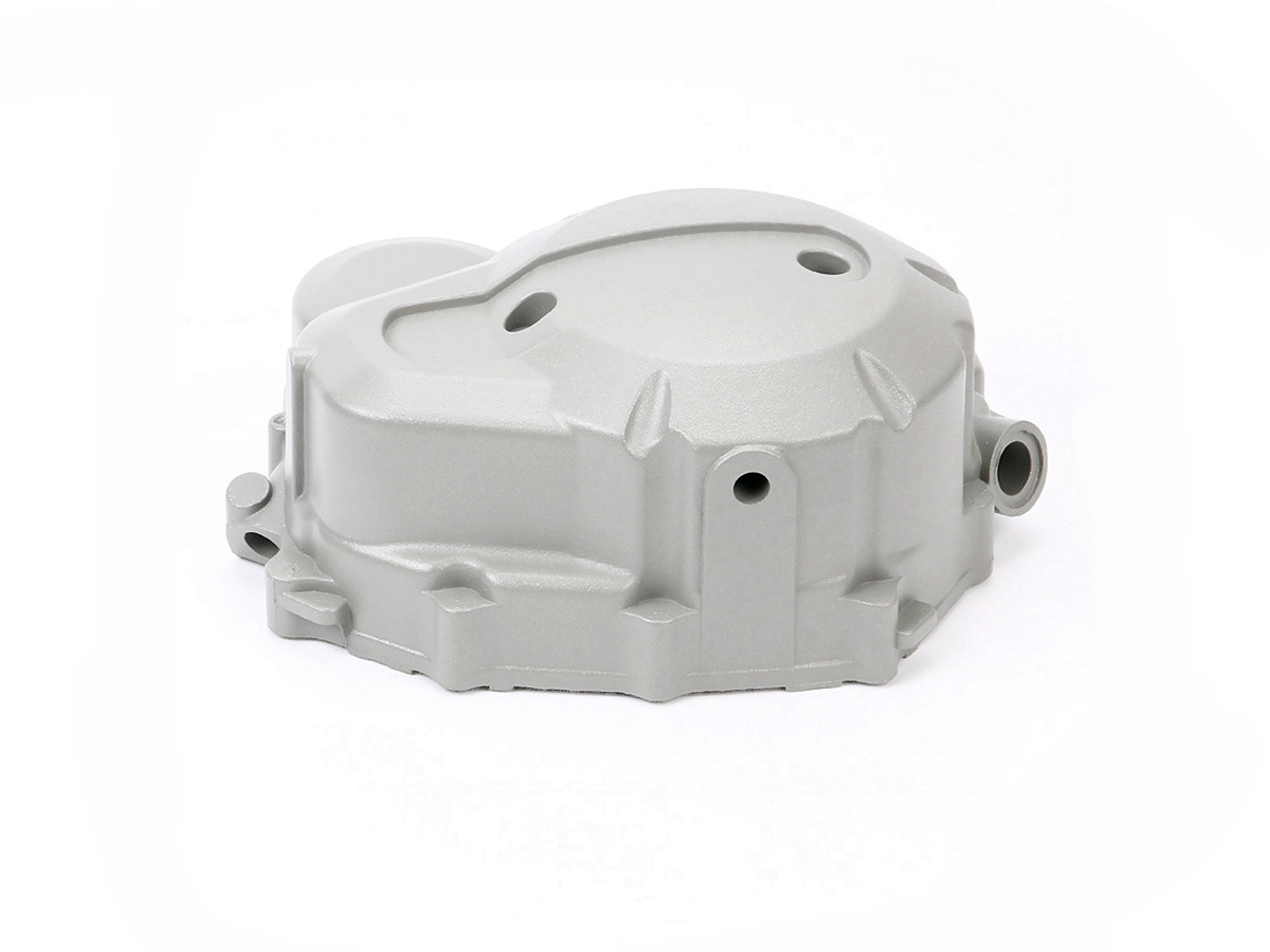
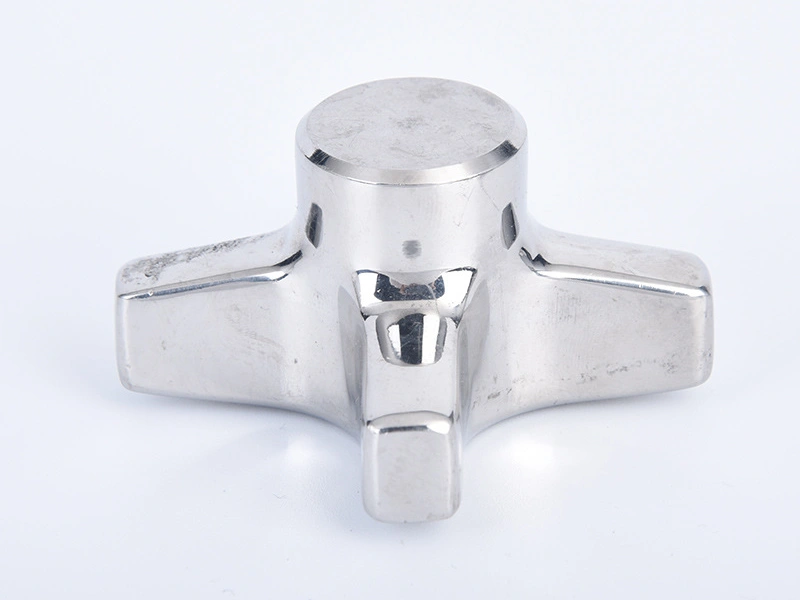
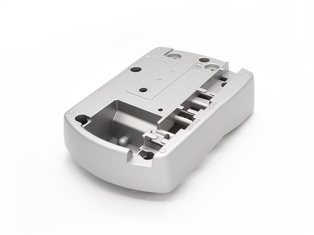
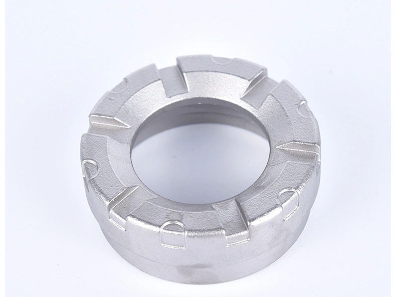
High-precision aluminum casting can be a strong production route for selected automotive engine components when the exact alloy and process, local casting integrity, machining datum strategy, thermal distortion, fluid boundaries, cleanliness, assembly, and serial-production controls match the component's duty. Common candidates include oil pans, timing and cam covers, front covers, pump housings, intake or charge-air housings, bearing carriers, brackets, transmission cases, and selected crankcase or structural housings. Cylinder heads, pistons, turbocharger hot-side parts, connecting rods, and highly loaded mounts require separate route decisions and must not be assumed to use conventional high-pressure die casting.
Precision in an engine component is functional. It means bearings remain aligned, gears retain contact, seals maintain compression, oil and coolant stay in their intended paths, fasteners retain preload, rotating parts clear their surroundings, and the assembly remains serviceable through temperature, pressure, vibration, and aging. A room-temperature CMM report or catalog alloy value cannot establish those outcomes.
Identify combustion engine, hybrid engine, range extender, transmission, oil management, cooling, air handling, accessory drive, or adjacent powertrain function. State whether the casting supports bearings, reacts belt or chain load, carries engine torque, contains oil or coolant, locates sensors, provides grounding, supports a seal, or merely protects internal mechanisms. Record the consequence of leakage, distortion, fracture, contamination, or misalignment.
Define hot idle, full load, cold start, heat soak after shutdown, thermal shock, repeated short trips, long-duration running, start-stop cycling, towing, altitude, transport, service, and foreseeable upset conditions. Provide pressure histories rather than one nominal value. Include pulsation, relief events, vacuum, proof or burst requirements where applicable, fluid chemistry, aeration, contamination, and drain-back behavior.
The vehicle architecture sets boundary conditions. Engine mounts, transmission joints, exhaust proximity, underbody impact, road splash, shielding, airflow, cooling circuits, fastener stack, gaskets, covers, brackets, and attached accessories all affect the casting. Use the complete assembly and mounting state when deriving requirements.
Aluminum die casting covers several routes. Conventional and vacuum-assisted high-pressure die casting can suit integrated thin-to-moderate sections and production repetition. Squeeze or semi-solid routes may be considered where the required local structure and properties justify them. Low-pressure, gravity, sand, and permanent-mold processes can be more appropriate for cylinder heads, complex cores, heat treatment, larger sections, or different integrity needs. The component specification must name the approved route, not merely "die cast aluminum."
Route selection should address cores and passages, projected area, wall distribution, local heavy nodes, heat treatment, welding, pressure boundary, fatigue demand, machining depth, volume, tool investment, capacity, and change maturity. A process with a fast nominal cycle can become uneconomic if it creates unstable porosity, distortion, machining breakout, leak failures, or excessive inspection.
A380 and ADC12/A383-type alloys are commonly screened for high-pressure cast housings, covers, pans, and cases where castability and integrated geometry matter. A360 may be considered where corrosion behavior or pressure-integrity design is important. AlSi12 variants can support fluidity and selected geometry. A356 and AlSi10Mg-type alloys often belong to routes and heat-treatment conditions that must be distinguished from conventional high-pressure die casting.
The designation alone does not establish elevated-temperature strength, fatigue, ductility, pressure integrity, corrosion, thermal conductivity, dimensional stability, or machinability. Specify chemistry, material standard, casting route, heat treatment or condition, sampling location, and property evidence. Oil, coolant, fuel vapor, combustion products, road salt, cleaners, mating metals, temperature, time, and load must be assessed together.
Material substitution needs controls. Recycled content, ingot source, returns, melt handling, iron and trace elements, hydrogen, oxide films, holding time, and contamination may affect process and product. Define incoming or melt checks, permitted adjustments, traceability, and approval for source or chemistry changes at the level required by the program.
Engine castings see constrained thermal expansion as well as mechanical load. Hot oil, coolant, exhaust proximity, bearings, fasteners, steel inserts, cold airflow, and local heat sources create gradients. A flange can be flat at room temperature and distort during heat soak; a bearing bore can move relative to a shaft as the housing and steel elements expand differently.
Use coupled thermal and structural analysis where consequence justifies it. Model realistic heat-transfer boundaries, material condition, contacts, gasket or joint stiffness, bolt preload, bearing loads, pressure, inertia, and assembly constraints. Correlate predicted temperatures and movement with instrumented assemblies. Material data must represent the relevant temperature, time, section, route, and production state.
Walls, ribs, bosses, bearing towers, windows, flanges, and fastener patterns should follow load and heat paths while remaining castable. Abrupt thick nodes can create shrinkage and thermal imbalance. Excessively thin or unsupported flanges can distort under gasket and bolt load. Use DFM review to coordinate function with parting, gates, runners, overflows, vents, vacuum where used, cooling, slides, ejectors, trim, and machining stock.
Pressure suitability depends on the full history, fluid, temperature, section, local discontinuities, port and gallery geometry, plugs, threads, seals, machining, and failure consequence. An oil pan, low-pressure cover, water-pump housing, oil-pump body, and high-energy hydraulic passage are not equivalent. The design authority must define proof, leak, pulsation, burst, vacuum, and functional requirements as applicable.
Map critical fluid zones before tool design. Position gates, overflows, vents, ejectors, slides, and likely discontinuity concentrations away from deeply machined passages and sealing boundaries where practical. Define allowable discontinuity types and evidence by zone. A global porosity percentage is rarely an adequate rule for a machined gallery.
Machining can open connected pores or intersect an oxide film. Impregnation or local repair may be permitted for some low-consequence applications, but it needs specified zones, process, identification, validation, and rejection limits. It must not silently replace control of casting design or the production process.
Engine precision usually resides in relationships: bearing centers to mounting planes, seal grooves to shafts, pump bores to galleries, dowels to joint faces, threaded holes to clamps, and covers to rotating envelopes. Establish functional datums from the assembled load path. Avoid datum schemes that are easy to inspect but disconnected from how the component locates in the engine.
Post-machining should account for as-cast variation, clamping distortion, residual stress, tool wear, burr direction, coolant, chip evacuation, washing, and final coating. Fixture the part in a state that predicts assembly where practical. Multiple operations need controlled datum transfer; deep passages need explicit burr and chip removal plans.
Specify profile, position, flatness, runout, coaxiality, surface texture, thread, edge, and stock only where function requires them. Include measurement access, temperature, support, filtering, datum simulation, uncertainty, and acceptance. A tighter number can increase cost and false rejection without improving sealing or alignment.
Seal performance depends on flange stiffness, surface, groove, gasket or seal material, compression, pressure, fluid, temperature, cover, fastener spacing, torque, relaxation, cleanliness, and aging. Test the complete joint. A machined flatness value does not compensate for a flexible cover, poor gasket selection, or uneven preload.
Threads and inserts must retain clamp load through heat cycles, vibration, corrosion, assembly, and service. Define engagement, local casting integrity, insert retention, washer, lubricant, torque or tension method, sequence, locking, reuse, and repair. Steel inserts and fasteners introduce thermal-expansion and galvanic questions.
Bearing and bushing interfaces need load direction, fit, housing stiffness, temperature, assembly force, lubrication, retention, and service review. Verify bore and shaft behavior under operating temperature and load. Check rotation, torque, alignment, contact pattern, noise, vibration, and wear after endurance testing.
Chips, burrs, casting flash, oxide fragments, abrasive media, release residue, machining coolant, fibers, coating, and corrosion debris can block oil jets, damage bearings, hold valves open, cut seals, or accelerate wear. A clean-looking casting can still contain harmful particles in galleries, threaded holes, pockets, and cross-drilled passages.
Define extraction method, particle size and mass limits where appropriate, prohibited particle types, test location, flushing, drying, preservation, packaging, storage, and assembly handling. Design drain and cleaning access. Validate washing against the actual geometry and production soils; a general wash-cycle description is not evidence.
Protect cleaned components from recontamination. Packaging materials, corrosion inhibitors, labels, trays, gloves, and transport vibration should not introduce fibers, residue, abrasion, or trapped moisture. Link packaging opening and line-side handling to the final cleanliness requirement.
A lightweight cover or case can change radiated noise, structural modes, gear whine transmission, and mount response. Rib layout, wall panels, bearing support, fastener pattern, gasket stiffness, attached brackets, shields, oil level, and temperature all influence noise and vibration. A static stiffness target does not predict the acoustic signature. Correlate modal and forced-response analysis with the assembled engine across speed, torque, temperature, and accessory states.
Oil control is also geometric. Drain-back paths, windage, splash, baffles, pickup clearance, aeration, crankcase ventilation, separator interfaces, and slope at vehicle attitude affect lubrication and emissions-related systems. Casting flash, core shift, burrs, adhesive squeeze-out, or a warped joint can restrict a small passage. Define flow and drainage checks for features whose blockage or leakage changes engine operation.
Crankcase and vapor boundaries can see pulsation, oil mist, condensate, fuel dilution, blow-by constituents, and freeze or sludge risks. Validate passages, seals, covers, valves, and attached hoses as a system. Keep coating, blasting media, wash residue, and packaging contamination away from oil-gas routes.
Many internal oil-wetted surfaces may remain controlled bare or machined, while external zones may need conversion, paint, powder, anodizing where alloy and function permit, or other protection. Select the complete layer system from substrate, road salt, condensation, heat, fluids, cleaners, electrical contact, fasteners, scratches, stone impact, and service. Do not infer underhood life from an isolated salt-spray duration.
Define masks at seal lands, bearing bores, threads, grounding pads, thermal interfaces, and adhesive zones. Film changes fit and preload; cure can affect seals or inserts; coating can hide or reveal substrate defects. Validate chipped edges, fastened joints, crevices, and fluid exposure in the assembled state.
Component function | Dominant risk | Production-intent evidence |
|---|---|---|
Oil pan or timing cover | Joint distortion, leakage, impact and oil compatibility | Final-state dimensions, aged assembly leak, vibration and impact checks |
Pump housing | Bore alignment, connected porosity, cavitation and debris | Machined integrity, cleanliness, pressure/pulsation and pump performance |
Bearing carrier or case | Thermal movement, fit, stiffness, lubrication and gear contact | Loaded hot alignment, endurance, noise, vibration and wear inspection |
Air or charge housing | Pressure cycling, temperature, joint leakage and contamination | Thermal-pressure cycles, leak, burst where required, and joint inspection |
Structural bracket | Fatigue, fastener slip, resonance and corrosion | Load spectrum, joint validation, component endurance and fracture review |
Prototype tests establish design learning; production-intent tests establish process relevance. Use nominated alloy, route, tool cavity, machining, cleaning, finish, seals, fasteners, and assembly. Include cold and hot function, thermal cycles, pressure cycles, vibration, fluids, corrosion, abuse, maintenance, and post-test inspection according to risk. One test does not validate every variant.
Connect material lot, melt, machine, die, cavity, insert, shot process, vacuum where used, thermal state, trim, heat treatment where applicable, machining line and tool, cleaning, finish, assembly, inspection, rework, and shipment. Establish controls for startup, restart, interrupted cycles, abnormal cooling, tool repair, machining alarms, wash failures, leaks, and nonconformance. Traceability depth should support practical containment and root-cause work.
Inspection must match the characteristic. Dimensional measurement, radiography, computed tomography, sectioning, penetrant testing, leak testing, cleanliness extraction, material testing, and functional tests have different access, resolution, sampling, uncertainty, and decision limits. Use inspection resources only after defining what each method must detect and how results control production.
Approve changes by affected risk. Alloy source, chemistry, die repair, insert replacement, gate or vent change, machine transfer, shot settings, heat treatment, machining fixture or program, wash chemistry, coating supplier, seal, fastener, packaging, and assembly torque can invalidate different evidence. The supplier should disclose changes before implementation according to the agreed plan.
First-off samples should verify the design and expose process risks; they should not be treated as serial capability by themselves. Production-intent runs need the nominated alloy source, machine, production die, cavities, thermal state, shot process, machining fixtures, cleaning line, finish, seals, fasteners, and inspection programs. Record hand work and deviations so that an exceptional sample is not mistaken for the stable process.
Build a characteristic matrix connecting function, drawing requirement, process control, measurement, sample frequency, acceptance, reaction, and validation. Include cavity-specific results and destructive evidence at justified intervals. Capability studies require a stable defined process and suitable measurement; a high index on an unimportant dimension cannot offset leakage, dirty galleries, or hot bearing misalignment.
Capacity review should use conforming output through casting, trim, machining, washing, finishing, assembly, and final test. Include planned maintenance, tool repairs, insert changes, changeovers, inspection bottlenecks, rework, packaging, and contingency. Validate restart and backup arrangements before a vehicle program depends on them.
Plan service demand and production end before serial launch. Engine components may be required long after peak vehicle production, when annual quantities no longer suit the original machine, tool condition, or supply chain. Define tool ownership, preservation, storage checks, restart approval, spare inserts, controlled programs and gauges, material availability, minimum runs, packaging life, and the disposition of obsolete revisions.
A proposed alternate route for late service parts needs engineering approval. Machining from billet or using another casting process can change material condition, porosity, stiffness, heat transfer, surface, and validation. Maintain configuration and traceability so a service part fits the engine and carries the authorized duty rather than merely matching its external shape.
Aluminum can reduce component mass relative to denser feasible materials, and die casting can integrate brackets, ribs, galleries, bosses, covers, and interfaces. The final saving depends on sections, inserts, reinforcement, fasteners, machining stock, finish, and eliminated parts. Weigh validated assemblies rather than quoting a density-based percentage.
Fuel or energy benefit depends on vehicle mass, drive cycle, powertrain, regenerative braking, gearing, aerodynamics, rolling resistance, payload, thermal management, and where the mass is removed. Engine-component mass can also affect center of gravity, mount loads, warm-up, service handling, and shipping. Vehicle simulation and testing must convert the mass change into an efficiency claim.
Compare total cost across tool, trials, qualification, casting, machining, cleaning, finishing, assembly, conforming yield, inspection, maintenance, changes, capacity, logistics, warranty, spares, and end-of-production service. Forging, machining, fabrication, polymer composites, gravity casting, and other routes may remain better for different loads, volumes, changes, or failure consequences.
Provide controlled 3D and drawing data, engine and component function, alloy/process restrictions, loads, vibration, temperature maps and cycles, pressure histories, fluids, cleanliness, corrosion, joints, bearings, seals, fasteners, inserts, safety consequence, target life, demand and variants, machining, finish, inspection, tests, traceability, packaging, capacity, continuity, service, and change requirements.
Ask the supplier to return exact alloy and route, assumptions, DFM exceptions, flow/vent/cooling/cavity concept, critical integrity zones, datum and machining plan, cleanliness route, finish system, tool maintenance and spares, samples, inspection methods, sub-tier controls, capacity, continuity, traceability, validation support, change triggers, repairs, and open risks.
A durable automotive engine casting is not defined by an alloy brochure or one tight dimension. It is a production component whose thermal geometry, fluid integrity, cleanliness, joints, and machined relationships remain fit across the engine's authorized duty and serial variation.
What aluminum alloys are most commonly used in engine die casting?
How does die casting compare to forged or machined engine components?
Can die cast engine parts withstand high temperatures and pressure?
What dimensional tolerances are standard for engine castings?
How can die casting improve fuel efficiency through weight savings?