English

Precision-Manufactured Aluminum Die Cast Housings for Consumer Electronics
Table of Contents
Define the product architecture before the casting
Choose die casting where integration creates value
Derive wall thickness from function and fill
Select alloy for casting, finish, and product function
Build the thermal path from chip to ambient
Coordinate EMI shielding with antennas and grounding
Engineer displays, connectors, buttons, and boards
Design ingress protection as a complete assembly
Design for drop, twist, and daily wear
Protect batteries and product-safety boundaries
Build the cosmetic surface system
Control cosmetic and dimensional defects at source
Validate housing functions with one decision table
Measure saleable yield and lifecycle cost
Design packaging, retail, and service together
Prepare an electronics housing RFQ
FAQs

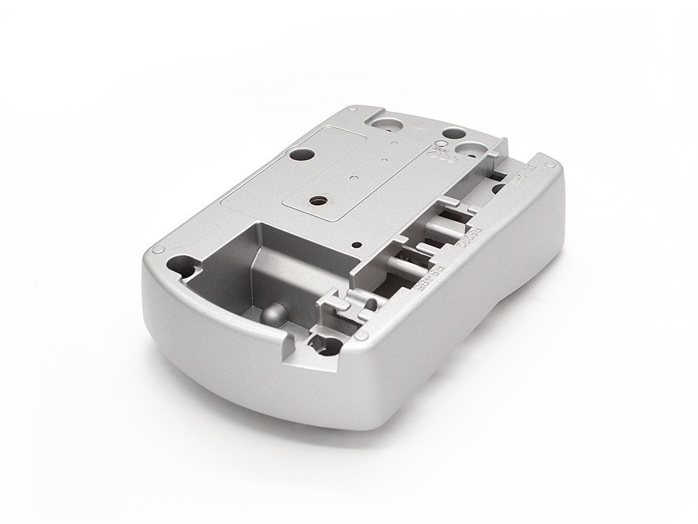
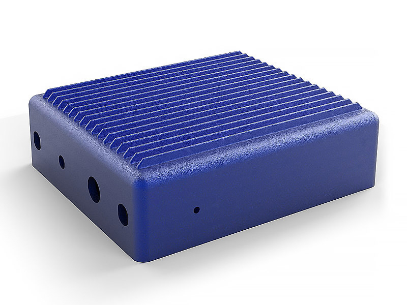
Consumer electronics aluminum die cast housing assessed for thermal path, EMI and antenna behavior, cosmetic finish, sealing, drop, assembly, and saleable yield Precision-manufactured aluminum die cast housings can combine structure, heat spreading, EMI containment, mounting, connector support, sealing flanges, and exterior form in consumer electronics. They are strongest candidates for speakers, routers, hubs, cameras, controllers, charging equipment, small appliances, internal frames, and selected wearable or handheld structures where a metal enclosure fits the antenna, touch, mass, appearance, and product-safety architecture. They are not automatically the best route for a smartphone or smartwatch exterior: RF transparency, skin contact, mass, finish, antenna breaks, glass bonding, sealing, and very high cosmetic expectations may favor wrought aluminum, stainless steel, polymer, composite, glass, or a hybrid assembly.

Housing precision is a product result. Buttons must feel consistent, connectors must align, displays and glass must sit correctly, gaskets must compress, boards must remain unstressed, antennas must radiate, heat must leave components without creating hot touch surfaces, and exterior panels must survive handling. A tight free-state CMM result or one polished sample cannot prove those outcomes at scale.

Define the product architecture before the casting

Identify product category, user, use posture, installation, market variants, service model, expected life, and price/appearance tier. Map display, battery, PCB, camera, speaker, microphone, motor, connector, button, antenna, sensor, thermal interface, gasket, adhesive, fasteners, labels, and cosmetic zones. State whether the casting is an exterior A-surface, internal mid-frame, heat spreader, RF shield, structural chassis, or enclosure half.

Define normal use and foreseeable abuse: hand oils, sweat, cosmetics, cleaners, food, humidity, condensation, rain, dust, lint, UV, temperature, charging, blocked vents, drop, twist, crush, cable pull, button cycles, transport, and repair. Product claims such as ingress code, drop height, touch temperature, wireless performance, or skin compatibility belong to the complete configured product and authorized test plan.

Set failure in user terms: cracked glass, loose connector, dead pixel, battery damage, uncomfortable temperature, intermittent RF, audible buzz, water entry, peeling finish, sharp edge, rocking on a table, visible gap, stripped thread, or inability to service. Those failures determine which housing characteristics deserve control.

Choose die casting where integration creates value

High-pressure aluminum die casting can form ribs, bosses, screw towers, heat-spreader pads, fins, connector walls, button guides, cable routes, gasket flanges, grounding features, branding recesses, and assembly datums. Integration can replace brackets, shields, heat spreaders, fasteners, and machining while reducing tolerance stack.

It also concentrates risk. One cold shut, pore opened by machining, chipped edge, distorted flange, or finish defect can reject a high-value multifunction part. Dedicated tooling makes late industrial-design or port changes expensive. Evaluate industrial-design maturity, annual demand, variants, visible-area yield, capacity, tool maintenance, and service before committing.

Compare feasible alternatives. Wrought machining may support sharp cosmetic edges, premium anodizing, rapid change, and low demand. Extrusion suits long constant sections. Stamping or sheet fabrication can suit covers and shields. Magnesium, zinc, polymer, composite, glass, and mixed structures offer different mass, RF, thermal, touch, finish, and assembly tradeoffs.

Derive wall thickness from function and fill

There is no standard wall thickness for every electronics housing. Choose nominal and local sections from flow length, alloy, gate/vent/vacuum concept, projected area, machine, tool thermal balance, stiffness, drop load, screw bosses, gasket compression, heat spreading, finish, and cosmetic acceptance. The minimum that fills one trial is not a production design limit.

Keep walls reasonably uniform where function permits and transition gradually. Heavy bosses and ribs can create hot nodes, sink, shrinkage, read-through, or finish variation. Very thin broad panels can warp, oil-can, buzz acoustically, or show assembly stress. Use ribs and curvature with care; a rib that raises stiffness can also create a visible shadow or trap powder.

DFM review should connect external styling and internal package to parting, gates, runners, overflows, vents, vacuum where used, slides, ejectors, trim, machining, cosmetic zones, and inspection. Design study should evaluate stable yield across cavities and tool age, not only nominal fill simulation.

Select alloy for casting, finish, and product function

A380 and ADC12/A383-type alloys are commonly screened for integrated high-pressure housings because of castability and general mechanical behavior. A360 or AlSi12 variants may fit selected corrosion, pressure-integrity, or geometry needs. AlSi10Mg-type names require an exact standard and route; they should not be assumed to produce wrought-like decorative anodizing in conventional high-pressure casting.

Alloy choice affects fill, soldering, shrinkage, machinability, thermal behavior, conductivity, corrosion, coating appearance, polishing, and recycling. Exact chemistry, melt practice, returns, trace elements, source, and process condition matter. Validate the final finish on production-intent substrate; high silicon, porosity, flow patterns, and intermetallics can remain visible after chemical or mechanical treatment.

For wearables and handheld products, assess skin-contact materials, nickel or other substance restrictions, sweat, cosmetics, cleaners, and galvanic couples in the complete finish system. Material designation alone does not establish regulatory or biocompatibility suitability.

Build the thermal path from chip to ambient

The housing can spread heat and provide fins or exterior area, but alloy thermal conductivity is only one resistance. Junction, package, solder, PCB, interface material, clamp pressure, flatness, cast wall, coating, airflow, orientation, dust, and user contact create the path. A cast heat-sink feature is valuable only when heat reaches it and ambient conditions remove the energy.

Map steady, burst, charging, wireless, gaming, motor, blocked-vent, sun, case/cover, and fault states. Limit component temperatures, battery exposure, display gradients, touch surfaces, adhesives, and seals according to the product plan. Thermal throttling can protect hardware but reduce performance; include control behavior in tests.

Integrated fins need fill, ejection, cleaning, finish, and handling review. Deep narrow fins can short-fill or trap coating; large fins can disturb acoustic paths or become sharp/drop-sensitive features. Machine thermal interface pads only where surface and flatness materially reduce contact resistance. Validate aged interface compression and assembly variation.

Coordinate EMI shielding with antennas and grounding

A conductive aluminum housing can support shielding when seams, openings, joints, coatings, fasteners, conductive gaskets, grounding pads, and cable/connector paths are designed as a system. Shielding effectiveness is frequency, field, source, aperture, contact, and configuration dependent. The casting alone has no universal dB rating.

Metal can also block or detune cellular, Wi-Fi, Bluetooth, GNSS, NFC, wireless charging, and other RF functions. Antenna windows, slots, polymer breaks, isolated regions, ground planes, matching, hand/head loading, display, battery, and regional band variants must be co-designed. A feature that closes an EMI seam can damage antenna efficiency.

Specify conductive contact zones and keep insulating finishes away or use qualified selective masks/treatments. Oxide, paint, powder, anodize, oils, corrosion, screw relaxation, and gasket compression affect continuity. Test radiated/conducted emissions, immunity, antenna performance, coexistence, ESD, and wireless charging in the complete production-intent device according to the authorized plan.

Engineer displays, connectors, buttons, and boards

Display and glass bonds need flange/profile, adhesive gap, surface preparation, cure, thermal expansion, drop strain, and repair strategy. A locally flat machined ledge can still twist after board, battery, cover, or fastener assembly. Validate glass stress and optical appearance across thermal and mechanical use.

Connector cutouts need location, datum, board tolerance, cable insertion load, shell grounding, gasket, external plug envelope, and repeated cycles. Buttons require guide alignment, travel, preload, seal, tactile switch position, coating thickness, and wear. Speaker and microphone features interact with acoustic volume, mesh, adhesives, water membranes, and pressure equalization.

PCB bosses should avoid board bending and solder-joint strain. Define standoffs, inserts, screw torque, washers, grounding, component keep-outs, and assembly sequence. Steel fasteners and inserts in aluminum need galvanic, relaxation, thread service, and strip/repair rules.

Design ingress protection as a complete assembly

The complete device carries an ingress result, not the casting. Trace paths through cast walls, machined ports, parting features, glass/display bonds, covers, gaskets, fasteners, connectors, buttons, speakers, microphones, vents, membranes, battery doors, and antenna windows. Define the exact target code/standard, orientation, operation, variants, preconditioning, test, and acceptance.

Place likely connected-discontinuity and deep-machining zones away from sealed boundaries where practical. Control flange stiffness, surface, grooves, edges, coating transitions, cover deflection, gasket compression, fastener torque, and cleanliness. Leak or pressure-decay screening can detect selected production defects when correlated, but it does not automatically reproduce the claimed dust/water test.

Test after aging and abuse relevant to the product: drop, twist, button/port cycles, cable pull, thermal cycling, UV, sweat, cleaners, seal compression set, and service opening. A new laboratory sample may pass while a dropped or repaired product leaks.

Design for drop, twist, and daily wear

Drop response depends on device mass, center of gravity, orientation, impact surface, temperature, case or accessory, glass, battery, board, fasteners, adhesives, and internal clearances. A stiff metal housing can protect one component while transmitting acceleration to another. Model and test the complete assembly across required orientations and conditions.

Inspect more than visible dents. Check glass/bond, battery deformation, connector movement, board cracks, solder joints, fastener preload, antenna contacts, gasket path, button feel, acoustic behavior, and hidden boss cracks. Re-test ingress or electrical safety where the drop could affect those functions.

Wear arises at pockets, tables, chargers, straps, docks, cables, buttons, and repair tools. Use boundary samples and test methods tied to real counterfaces, force, motion, contamination, sweat, cleaners, and time. Hardness or coating thickness alone does not predict scratch visibility or gloss change.

Protect batteries and product-safety boundaries

The housing can restrain, shield, or spread heat around a battery, but it can also create crush points, sharp internal edges, conductive short paths, or thermal coupling. Define cell clearances, swelling allowance, adhesive, foam, insulation, tabs, connectors, venting, drop intrusion, screw length, and service tool paths. Control burrs, loose inserts, conductive debris, and coating damage near energized parts.

Grounding and insulation must follow the product's electrical architecture. Cast walls, fasteners, coatings, gaps, creepage/clearance paths, accessible metal, connectors, charging circuits, and fault energy need evaluation under applicable product requirements. A metal enclosure does not automatically improve electrical safety.

After drop, thermal abuse, connector damage, water exposure, or repair, inspect battery deformation, insulation, fastener penetration, board contact, and hidden cracks before resuming charge tests. The product owner controls safety certification and market claims; the housing supplier provides controlled geometry, material, finish, and traceability evidence.

Build the cosmetic surface system

Define A/B/C cosmetic zones, viewing distance and angle, lighting, color, gloss, texture, grain direction, parting/gate/ejector visibility, allowed flow marks, pores, scratches, dents, coating particles, edge coverage, logo, and approved boundary samples. "Premium" and "flawless" are not inspection criteria.

Mechanical preparation, polishing, anodizing where suitable, conversion, paint, powder coating, laser marking, printing, and in-mold features create different process signatures. Blasting can expose pores and create texture variation; polishing can reveal flow; coating can bridge edges or emphasize substrate defects. Do not use finish to hide an unapproved cold shut or crack.

Color and gloss depend on substrate, lot, preparation, layer chemistry, thickness, cure, geometry, rack contact, and measurement. Establish master and boundary samples with instrument correlation. Manage multi-part color harmony under the product's real lighting and viewing conditions.

Control cosmetic and dimensional defects at source

Map likely short fill, cold shut, flow line, oxide, gas/shrinkage, sink/read-through, flash, mismatch, ejector, drag, crack, distortion, machining mark, burr, handling, and finish defects to their process sources. Gate/vent/overflow design, die thermal balance, shot profile, vacuum where used, spray, cooling, ejection, trim, tool surface, and handling need connected controls.

Use separate final-state controls for dimensions and appearance. Post-machining establishes connector, button, display, gasket, datum, and thermal features but can open pores or create burrs. Coating adds thickness and can change fit. Inspect in the state that reaches assembly.

Automated or visual inspection needs controlled lighting, orientation, distance, training, defect library, gauge studies, and disposition. Cameras can improve consistency for defined signatures but do not decide functional severity by themselves. Trace cavity, lot, tool maintenance, surface batch, rework, and pack-out to contain trends.

Validate housing functions with one decision table

Housing function

Dominant risk

Production-intent evidence

Heat spreader or finned enclosure

Interface resistance, hot touch, throttling and finish buildup

Thermal map and performance across power, orientation and aging

EMI/RF enclosure

Seam leakage, contact aging and antenna detuning

Emissions/immunity, continuity, antenna and coexistence tests

Display/glass frame

Warp, bond stress, gap and drop transfer

Final assembly geometry, optical inspection, thermal/drop tests

Ingress boundary

Porosity, flange/joint, port, vent and seal aging

Aged configured product ingress plus correlated production screen

Cosmetic exterior

Substrate read-through, color/gloss, scratches and edge damage

Boundary samples, controlled visual/instrument checks and wear

Measure saleable yield and lifecycle cost

Fast casting cycles do not guarantee low product cost. Track saleable yield after casting, trim, machining, cleaning, finishing, marking, assembly, functional test, visual inspection, packaging, and retail handling. A cosmetic reject after full finishing has a different cost from an early casting reject.

Model tooling, samples, design changes, cavities, machine/finish capacity, inspection, rework, scrap, variant changeovers, color lots, inventory, packaging, warranty, service, and end-of-life spares. High visible-area requirements can make a slower but more predictable route economic. Use actual demand scenarios rather than a universal break-even volume.

Plan product revisions and seasonal variants. Inserts can support logo or port changes but may affect parting, appearance, and dimensions. Preserve tooling, programs, boundary samples, finish masters, gauges, and approved configurations for service while preventing obsolete parts from mixing with current builds.

Design packaging, retail, and service together

Final appearance can be lost after inspection. Define tray and separator contact, protective films, bags, labels, desiccants where appropriate, gloves, stacking, transport vibration, warehouse temperature/humidity, retail display, and unboxing. Films and foams can imprint, transfer chemistry, trap moisture, or change gloss. Validate representative packed shipments and shelf dwell.

Service opening can scratch coatings, strip threads, distort gasket flanges, damage antennas, or replace the wrong screw. Provide tool access, disassembly sequence, replaceable seals, torque, adhesive removal, cosmetic protection, inspection, and reassembly tests. Decide which scratches or bent features require housing replacement rather than touch-up.

Recycling and material recovery depend on alloy identification, inserts, coatings, adhesives, labels, batteries, and ease of separation. A highly integrated housing can reduce parts during assembly yet complicate repair or end-of-life disassembly. Include those tradeoffs in architecture and cost reviews instead of treating recyclability as an alloy-only benefit.

Prepare an electronics housing RFQ

Provide controlled geometry, product architecture, use/abuse, mass and touch targets, heat sources and power states, RF bands/antennas, EMI/ESD, ingress claim, display/glass, connectors/buttons/acoustics, battery, loads/drop, materials/substances, cosmetic zones and boundary samples, alloy/route restrictions, machining, finish, dimensions, tests, demand/variants, packaging, service, traceability, and change requirements.

Ask the supplier to return exact alloy and route, DFM exceptions, wall/fill/thermal concept, gates/vents/overflows/cavities, cosmetic zoning, datum and machining plan, complete surface route, masks, sub-tiers, assembly assumptions, samples, inspection methods, test support, expected saleable yield, tooling, capacity, color/variant controls, traceability, repairs, change triggers, and open risks.

A precision consumer electronics housing succeeds when the assembled product remains cool enough, electrically and wirelessly functional, aligned, sealed where claimed, durable, visually acceptable, and producible at saleable yield. Casting precision is one contributor to that outcome, not the outcome itself.

FAQs

  1. What is the standard wall thickness for aluminum die cast electronics housings?

  2. Which aluminum alloys are best for smartphone or smartwatch enclosures?

  3. How are cosmetic and dimensional defects controlled in die cast housings?

  4. What finishing options are available for premium consumer electronics?

  5. Can aluminum die cast housings integrate with heat sinks or EMI shielding?
Copyright © 2026 Diecast Precision Works Ltd.All Rights Reserved.