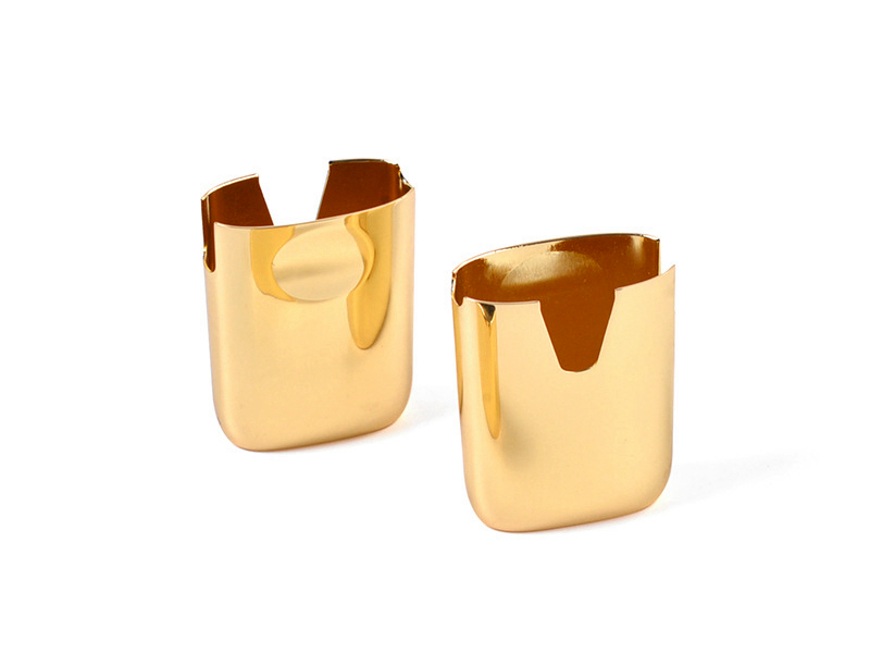
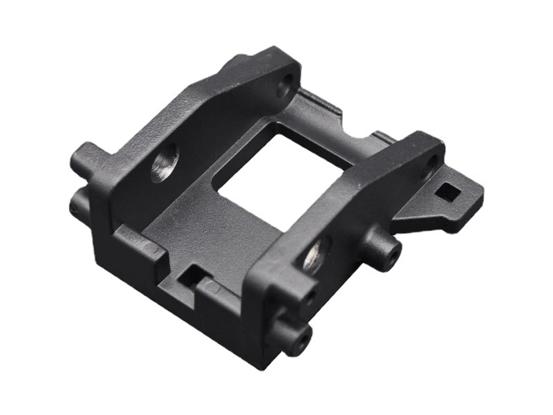
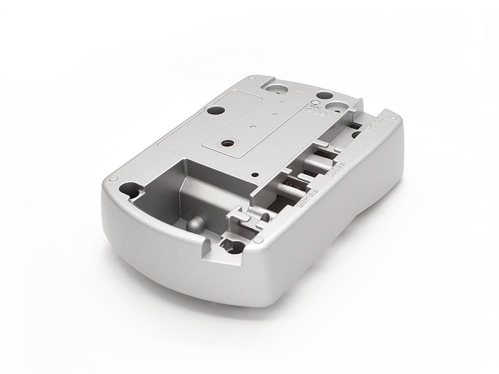
Precision zinc alloy die casting is a strong candidate for consumer-electronic casings, internal frames, bezels, control parts and weighted bases when the design values compact detail, stiffness, crisp interfaces, controlled seams and a plated or coated appearance more than minimum mass. It is not automatically the right choice for a large handheld shell or an enclosure surrounding active antennas. The decision must compare a finished, assembled Zamak design with aluminum, magnesium, stamped metal, machined metal and coated polymer alternatives.
The casing cannot be released from an attractive rendering alone. Industrial-design surfaces, display and lens gaps, button feel, speaker openings, connector ports, antenna windows, battery access, drop loads, shielding, grounding, heat paths, finish build, fingerprints, cosmetics and assembly repair all interact. A casting that looks smooth before coating may reveal flow witness, pores or polishing distortion later. The RFQ therefore needs surface zones and functional evidence, not a broad request for a “premium finish.”
State whether the Zamak component is an exterior A-surface shell, internal chassis, bezel, hinge or stand part, button, knob, camera ring, connector surround, shield frame, decorative badge or weighted base. Exterior shells carry touch, appearance and drop risks. Internal frames carry PCB, display, battery, speaker, haptic motor, connector and fastener alignment. Small trim parts may be driven mainly by edge definition and finish.
List the complete product interfaces: plastic covers, glass or display, lens, elastomer, adhesive, screws, inserts, snaps, PCB, RF ground springs, thermal pads, battery, magnets, microphones, speakers, vents, buttons, switches and cables. Identify service access and which joints are opened during repair. Zinc should be credited only with the functions the assembled stack demonstrates.
Define failure in user terms. Rocking on a table, a proud lens, uneven display gap, sticky button, creak, rattle, radio desense, excessive touch temperature, coating chip, visible sink or color mismatch can reject a device even when the casting drawing dimensions pass. These user-level failures should trace to measurable characteristics and test configurations.
Zinc die casting can consolidate bosses, ribs, port frames, keypad features, grounding lands, decorative edges and internal supports. Its density can create a deliberate stable or substantial feel in a desktop control, audio product or weighted stand. The same density may work against a wearable, phone-sized handheld device or moving mechanism. “Premium feel” must be a product decision, not a substitute for mass and balance targets.
Aluminum or magnesium may reduce mass but require different wall, corrosion, surface and grounding solutions. Stamped sheet can be thin and light but introduces formed limits and seams. Machined metal supports development or premium low-volume geometry but has different cost and material use. Coated polymer integrates dielectric antenna windows and low mass, while coating adhesion, creep, shielding layers and threaded interfaces need attention. Hybrid construction often puts metal only where stiffness, ground, shielding or touch is valuable.
Architecture | Why it may fit | Consumer-device risk | Release evidence |
|---|---|---|---|
Zamak exterior or mid-frame | Crisp compact features, stiffness, finish options and integrated ground lands | Mass, antenna obstruction, visible casting/finish defects and galvanic joints | Finished assembly cosmetics, drop, RF, touch temperature, wear and corrosion |
Aluminum or magnesium shell | Lower mass with metal stiffness and heat spreading | Alloy/process-specific surface, corrosion, joining and thin-feature limits | Optimized-design comparison at equal device function |
Stamped metal | Thin, light shell and established shielding construction | Seams, springback, edge treatment and separate internal supports | Gap/flush, seam, drop, finish and assembly study |
Coated polymer | Low mass, dielectric RF zones and molded tactile geometry | Creep, coating wear, grounding, screw retention and perceived stiffness | Aged assembly, RF, wear, impact and coating continuity |
Hybrid shell and chassis | Places each material where its function is useful | More interfaces, stack variation, adhesive/joint durability and repair complexity | Complete stack under mechanical, thermal, RF and cosmetic sequences |
Zamak 3 is a sensible baseline for many housings and trim parts because it combines established casting behavior, dimensional response and finishing potential. Zamak 5 can enter the comparison when loaded bosses, hinge features, threads, lugs or wear surfaces deserve more emphasis. Zamak 7 may help fine details or thin compact regions where fluidity is a genuine DFM constraint. No grade is “the cosmetic alloy” without the die, process and finish route.
Zinc alloy specifications should be tied to the correct standard, chemistry and supplied condition. Control impurities, mixed alloys, melt contamination and internal returns because finish defects and long-term behavior can begin in metal control. Verify important properties in representative casting sections after machining, polishing and finish.
Use a weighted trade study for mass, stiffness, impact, screw or hinge load, detail, finish, aging, corrosion, supply control and cost. For a visible enclosure, finish yield may be more influential than nominal material price. For a weighted base, density may remove separate ballast. For a wearable bezel, the same density may end the Zamak option before detailed tooling work.
Mark A, B and hidden surfaces on the model or drawing. For each zone, define viewing distance, angle, lighting, color, gloss, texture direction, master sample and allowable defect size, count and spacing. Separate uninterrupted display surrounds and branded faces from low-visibility edges, internal areas, seal lands, conductive contacts and adhesive zones. “No defects” is not an inspectable standard.
Place gate remnants, overflows, parting line, ejector witness, slide witness and rack contacts where their removal or appearance is acceptable. A polished face may expose subsurface pores; blasting may reveal flow differences; a high-gloss coating may magnify waviness. The desired final look must influence die layout and flow strategy before steel release.
Define edge language as manufactured geometry. Sharp visual edges still need safe touch, coating coverage, trim and dent resistance. Cosmetic radii, chamfers, reveal lines and intentional texture breaks can manage parting or color transitions. Do not rely on manual polishing to create an uncontrolled product edge.
Minimum wall is not a catalog number. It depends on alloy, flow length, projected area, local feature, gate path, venting, machine, die temperature, surface requirement, ejection, ribs, openings and load. A small local membrane beside a gate is not evidence that a broad decorated shell can use the same section. Use zinc thin-wall DFM to frame trials, then validate the production geometry.
Keep nominal walls reasonably uniform and transition thickness gradually. Heavy bosses behind an A-surface can feed shrinkage, sink or waviness; isolated thin zones can misrun or distort. Core bosses, support them with proportionate ribs and separate them from visible faces where possible. Openings for displays, cameras, speakers and ports reduce stiffness and create flow splits that must rejoin without unacceptable witness.
Stiffness belongs to the assembled device. Include cover, display adhesive, PCB screws, battery, internal brackets and gasket loads in distortion studies. Evaluate drop orientation and local impact, not only static center deflection. If an extremely thin wall requires aggressive process settings but produces poor ejection or cosmetic yield, a small mass saving may not survive production economics.
Select datums from assembly function: display seat, PCB plane, port centerline, hinge axis, lens bore or exterior support feet. Do not dimension every feature from a cosmetic freeform face. Allocate variation among casting, machining, finish, inserts, adhesives, glass, molded covers and assembly fixtures. A tight casting tolerance cannot compensate for an undefined stack.
Buttons and knobs need travel, side clearance, return force, switch alignment, finish build and contamination allowances. Port openings need connector position, cable plug envelope, chamfer, shell ground contact and user insertion abuse. Speaker and microphone openings need acoustic path, mesh or membrane, adhesive and burr controls. Keep flash and loose finishing media away from electrical and acoustic cavities.
Use post-machining only where the functional datum, thread, bearing, seal or critical alignment justifies it. Machining can expose pores and creates chips, burrs and a different surface condition. Define whether machining occurs before or after a given finish layer and how the exposed region is protected.
A conductive zinc enclosure can support shielding, but it can also block or detune an internal antenna. The RF architect should define antenna type, band, position, ground plane, keep-out, dielectric window, cable and user interaction. Metal should not cross a required radiation aperture merely because it simplifies the casting. Validate over device orientations, battery states, accessories and realistic hand or body effects as applicable.
EMI containment depends on seams, display openings, buttons, ports, speakers, vents, cable paths, conductive gaskets or foams, spring contacts, finish, screw spacing and PCB/chassis grounding. Bulk zinc conductivity does not predict emissions or immunity. Map the path from noisy circuits and cables to the casing and from casing joints to system ground.
Paint, powder and some decorative layers insulate contacts. Mark conductive lands and masks; control contact pressure, finish chemistry, oxidation, contamination and wear. Verify bond or joint resistance where it is meaningful, then test the complete electronics in the required configuration and frequency range. Include environmental and assembly cycles that can change seams or contacts.
Zinc can spread heat through an enclosure, but thermal performance starts with processor, power component, battery, charger and display losses. Define thermal pads, graphite or spreader layers, screw or clamp pressure, contact area, interface thickness, airflow and insulation. Casting porosity is rarely the first thermal question; an air gap or compressed pad variation can dominate the path.
Separate component temperature, battery limits and user touch comfort. A metal shell that lowers a chip temperature may create a hot spot at a grip surface. Model realistic operating modes, charging, ambient, orientation and accessory covers, then correlate with instrumented production-intent assemblies. Coating color, thickness and texture can change external heat transfer and touch perception.
Keep battery safety ownership with the battery and product design authorities. The shell may provide impact protection, spacing or heat spreading but does not by itself establish thermal-runaway containment or product certification. Define vents, pressure relief and flame or ejection paths at complete-device level where those risks apply.
Zamak can support qualified multilayer plating, paint, powder and mechanical preparation routes. The choice depends on metallic or opaque appearance, color/gloss/texture, touch, sweat and cosmetics exposure, UV, abrasion, drop/chip behavior, corrosion, conductive lands, dimensions, substances, repair and volume. An attractive coupon does not prove coverage and color on the production casting.
Zinc finishing options must include cleaning, activation, leveling or polishing, underlayers, top layer, masks, rack points, cure, inspection and packaging. Mechanical brushing or polishing direction should align with product geometry and avoid rounding gaps, logos and edges. Laser marks and printed graphics need adhesion, contrast, wear and registration evidence on the full layer stack.
Define tactile claims through samples and tests. Soft-touch coatings may change friction, attract contamination or age differently from hard paint. High-gloss faces reveal waviness and fingerprints. Fine matte texture can hide small variation but trap soils. Use approved limit samples after relevant handling, skin-contact simulants, cleaning, temperature, humidity, abrasion and drop exposure selected by the product owner.
Gate, runner, vent, overflow, cooling, ejection, slides and inserts should be reviewed with the marked cosmetic model. Locate flow joins and overflows deliberately around display windows, long edges, logos and high-gloss planes. Prevent drag, galling and ejector distortion. Replaceable inserts can protect fine ports or text, but their witness must fit the surface standard.
Plan how castings are trimmed, handled, stored, polished, racked, coated and transported. Part-to-part contact can dent a soft zinc edge before finishing; hooks can mark a visible face; polishing fixtures can distort a thin rim. Returnable trays, separators, gloves and orientation controls can be product requirements rather than packaging decoration.
Tool and die planning and finish timing should include appearance trials and limit-sample approval, not only first metal. Multiple cavities need cavity-specific surface and dimensional review. A correction that improves fill may move a witness onto the A-surface; a new polishing step may improve gloss but reduce an edge or gap. Keep linked tool, process and finish changes under approval.
Build samples from production-intent alloy and cavities, trimming, machining, polishing, finish, inserts, glass, plastic covers, adhesives, gaskets, PCB, battery, ports, controls, speakers, antennas, ground contacts, fasteners and controlled assembly tools. Inspect gaps, flushness, rocking, button force/travel, port fit, visual surfaces, mass and feel before and after relevant conditioning.
Mechanical validation can include controlled drops, impacts, torsion, squeeze, hinge or stand cycles, connector insertion, button use, screw service and packaging transport as applicable. Environmental work can include temperature, humidity, thermal cycling, sweat or skin-contact media, household chemicals, UV, abrasion and corrosion. The product owner defines methods, severity, sample count and acceptance.
Electrical work may include ground continuity, emissions, immunity, RF performance, antenna efficiency or sensitivity, acoustic performance, touch sensing and thermal behavior according to the architecture. Test before and after events that can move a seam, damage finish or relax a contact. A bare empty housing test may support diagnosis but cannot release the finished device.
Use controlled master and boundary samples under specified lighting, orientation, viewing time and distance. Define zones, defect vocabulary, color/gloss/texture method, measurement locations, visual inspector qualification and escalation. Instrument readings help, but a single roughness or gloss value does not describe waviness, flow witness, orange peel, metallic flop, edge coverage or a localized pit.
Trace alloy and melt lot, die cavity, process window, trim, machining, polishing station and media, rack position, finish bath or paint lot, cure, inspection, handling and packaging. Link repeated cosmetic defects to cavity and surface-process history. Do not blend or repair visible parts without approved methods and a way to identify the disposition.
Control changes to alloy source, die steel or insert, gate and vent, release agent, shot settings, trim, polishing compound or media, cleaner, plating layers, paint formulation, colorant, cure, rack, masking, laser mark, assembly fixture and packaging. Recheck dimensional, cosmetic, RF, ground, thermal and durability effects according to the changed interface.
Provide released CAD and drawings, surface-zone model, part role, device stack, annual and lot demand, target mass and balance, loads, drop and service model, datums, gap/flush, ports and controls, antenna and EMI architecture, ground lands, thermal interfaces, finish stack, color/gloss/texture, graphics, substances, tests, inspection, traceability, packaging and change rules.
Ask suppliers to return alloy specification, alternative architecture, casting DFM, wall/flow review, gate/vent/ejection and cosmetic-witness plan, machining, finish pretreatment/layers, masks and rack contacts, tolerance stack, tooling and gauges, sub-tiers, appearance sample plan, validation, production controls, repair, exceptions and dated assumptions. Quotes are comparable only when the same finished evidence and cosmetic yield boundary are included.
Release the zinc casing when production-intent devices meet appearance, touch, assembly, mechanical, thermal, RF/EMI and durability requirements with controlled manufacturing records. Zinc alloy die casting earns its place when integrated geometry and finish produce a better whole-device result. It should not be selected from an isolated strength value, a smooth sample plaque or a promise of a universal minimum wall.