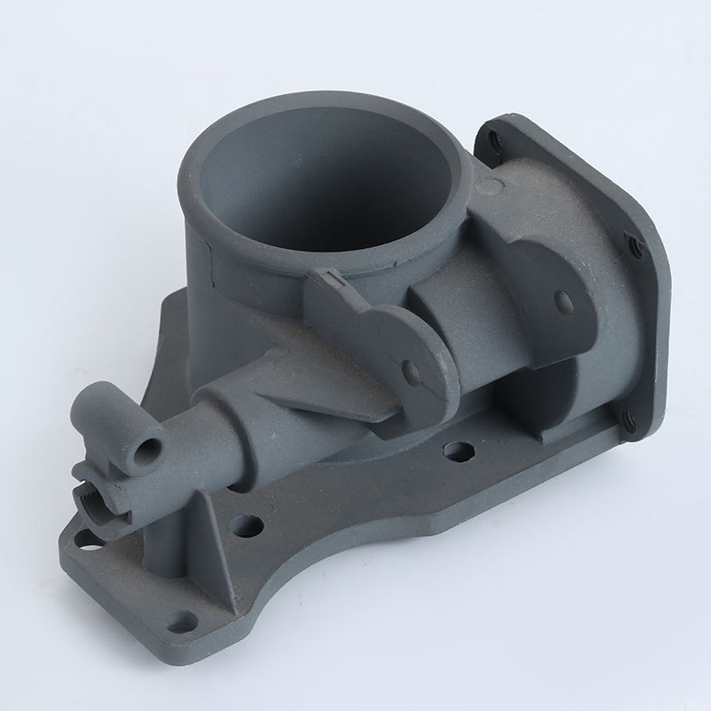
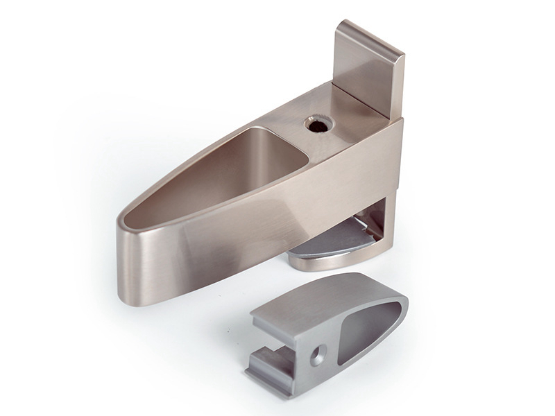
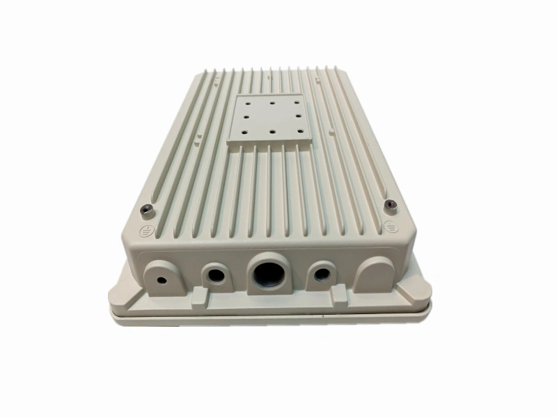
High-Strength Aluminum Alloy Die Casting for Industrial Machinery Components
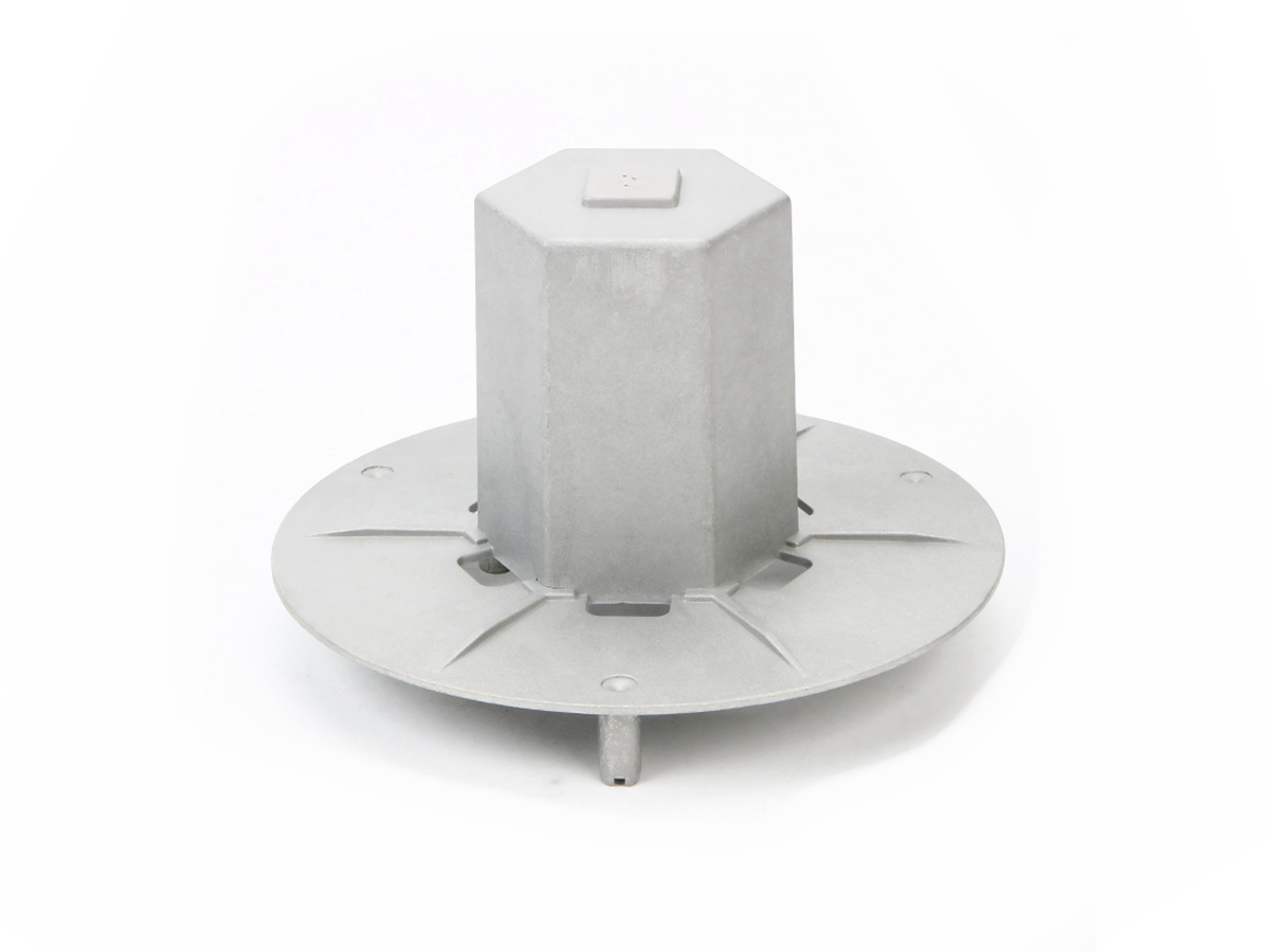 High-strength aluminum alloy die casting is a sound route for industrial machinery components when the casting carries defined loads through controlled sections and interfaces, remains stiff enough for alignment, survives the real duty cycle and environment, and can be inspected and maintained as required. Good candidates include motor and gearbox housings, bearing carriers, actuator bodies, sensor and control enclosures, guarded brackets, pump covers, robotic structures, and mounting frames. The process is a poor choice when a highly concentrated load, severe impact, bearing wear surface, welding requirement, pressure boundary, temperature, or safety consequence cannot be supported by the selected alloy, geometry, process route, and validation plan.
Calling a casting "high strength" does not settle that decision. Tensile data from a handbook or separately cast specimen do not establish stiffness, fatigue life, bolt retention, bore alignment, pressure integrity, impact resistance, or survival of defects in a finished component. Industrial buyers need a component-level argument: load cases, failure modes, alloy and casting route, critical zones, machining and surface state, inspection sensitivity, assembled tests, and production change controls.
Define the machinery function and consequence
Start with the machine, not the alloy list. Identify whether the part locates rotating shafts, supports a motor, closes a lubricated gearbox, guides an actuator, carries a robot axis, holds a guard, routes coolant, protects controls, or connects a moving assembly. State what loses function if the casting cracks, deflects, loosens, leaks, corrodes, or wears: alignment, containment, operator protection, product quality, uptime, or only appearance.
Map normal, transient, misuse, transport, installation, jam, emergency-stop, tool-crash, and maintenance loads. Include gravity, belt or chain pull, torque reaction, bearing forces, cylinder pressure, acceleration, vibration, shock, cable and hose loads, fastener preload, thermal expansion, assembly misalignment, lifting, and impacts from handled material. Frequency, sequence, direction, temperature, and load ratio matter. A rarely applied overload and millions of lower cycles create different design and validation questions.
Define interfaces and restrictions early: shaft and bearing alignment, seal compression, gasket flange, motor face, rail or frame mounting, dowels, threads, inserts, wear strips, hydraulic ports, sensor air gaps, grounding, guards, lifting points, and service tools. These interfaces often govern stiffness and local integrity before bulk tensile strength becomes the limiting property.
Choose die casting for integration, not for an alloy label
High-pressure aluminum die casting can integrate ribs, bosses, bearing supports, cable routes, lubrication channels, sensor mounts, cooling fins, covers, guards, datum pads, labels, and assembly features. Integration can remove fabricated brackets and fasteners, reduce machining, control relative feature location, and lower moving mass. Those benefits are strongest when demand and design maturity justify dedicated tooling.
Integration also raises the consequence of one defect or late design change. A pore opened in a seal groove, distorted bearing span, cracked boss, damaged coating, or inaccessible service fastener can reject a component containing many functions. Compare the casting with fabrication, extrusion, forging, sand or gravity casting, machined billet, polymer, and hybrid structures. The right comparison uses the final installed function, not raw material price or casting cycle time.
Separate strength, stiffness, fatigue, and stability
Strength addresses yielding, fracture, bearing, tear-out, thread stripping, and local crushing. Stiffness controls shaft alignment, gear mesh, seal face opening, sensor position, actuator guidance, resonance, and tool accuracy. Aluminum's elastic modulus is lower than steel's, so a same-shape substitution can deflect too much even when a static stress check passes. Geometry, load path, rib orientation, closed sections, joint spacing, and boundary conditions must recover the required stiffness.
Fatigue is sensitive to surface condition, cast discontinuities, section transitions, residual stress, machining marks, corrosion, mean stress, and load spectrum. Do not infer component fatigue from ultimate tensile strength. Evaluate likely initiation zones at boss roots, ribs, fillets, bearing seats, bolt holes, gates, ejector features, machined surfaces, and tool repairs. The acceptable discontinuity depends on its type, size, orientation, location, stress state, and consequence.
Creep or relaxation may matter around hot motors, brakes, pumps, heaters, and fastener joints. Temperature can change material behavior, gasket compression, bearing fits, adhesive performance, lubricant, coating, and alignment. Define hot and cold operating states, start-stop transients, thermal gradients, blocked cooling, and shutdown conditions rather than quoting one room-temperature property.
Select the exact alloy and process route
A380 and ADC12/A383-type compositions are commonly screened for integrated high-pressure cast geometry because they combine fill behavior, general mechanical performance, machinability, and established processing. A360 or AlSi12 variants may fit selected corrosion, pressure-integrity, or fill requirements. These names are starting points, not strength rankings.
A356 is often associated with gravity, low-pressure, or other routes and heat-treated conditions. It must not be inserted into a high-pressure die-casting decision table without naming the exact process, material standard, heat treatment, section, and qualification basis. Heat treatment can improve selected properties in suitable routes but may also cause distortion, blistering, dimensional movement, or additional inspection burden. The quote must state exactly what will be supplied.
Review chemistry, melt practice, returns, inclusions, gas, oxide control, die soldering, castability, machinability, corrosion, thermal conductivity, coating response, availability, recycling stream, and property variation. Obtain data relevant to the intended process and section. Where the design depends on a property, define how that property is established, sampled, linked to the casting, and handled after a material or source change.
Design the load path and casting flow together
A mechanically attractive rib network can be difficult to fill or eject. A flow-friendly heavy junction can shrink, distort, or become a fatigue concern. DFM review must connect load paths with parting, gates, runners, overflows, vents, vacuum where used, slides, inserts, ejectors, trim, tool cooling, machining, and inspection.
Keep adjacent sections reasonably uniform where function allows and use transitions that avoid abrupt stiffness and thermal changes. Core heavy bosses and pads where practical. Ribs should follow load transfer and stabilize panels without creating isolated hot nodes, inaccessible pockets, sharp edges, coating traps, or tool steel too weak to survive. Fillets reduce local stress only when their size, surface, and neighboring geometry support both casting and load flow.
Do not make every wall thicker as a response to uncertainty. Extra metal can increase projected area, solidification time, shrinkage, distortion, mass, thermal gradients, and tool demand. A local steel insert, bushing, wear plate, or separate bracket may be more honest than forcing cast aluminum to perform every contact and wear function.
Engineer joints, bearings, threads, and wear surfaces
Bearing bores and shaft spans need final assembled alignment under bolt preload, temperature, belt or gear load, and housing support. A free-state CMM report can miss bore movement after cover assembly or mounting to a distorted frame. Define datum strategy, machining sequence, fixture restraint, bearing fits, lubrication, retention, and how paired bores are measured.
Threads and inserts require engagement, local wall, boss integrity, torque, preload, relaxation, repeated service, galvanic compatibility, and repair rules. A steel insert can improve wear or serviceability but adds thermal expansion mismatch, installation load, corrosion, pull-out, and traceability questions. Test the complete joint using production-intent holes, fasteners, coatings, washers, lubricant, and tightening method.
Sliding, rolling, abrasive, or impact contact usually needs more than base aluminum. Use replaceable bushings, bearing races, liners, hard inserts, coatings, or redesigned contact paths as the duty requires. Contamination from dust, chips, slurry, grit, and poor lubrication can dominate nominal hardness. Plan replacement access before combining the wear item permanently with the casting.
Control porosity and other discontinuities by zone
Gas pores, shrinkage, oxide films, cold shuts, cracks, inclusions, soldering, flow lines, and machining-opened voids are not interchangeable. Their significance changes by zone. A small rounded pore in a low-stress cover may be acceptable while a planar discontinuity at a loaded boss, seal land, thread, bearing seat, or pressure wall may not be.
Classify critical structural, fatigue, pressure, sealing, machined, cosmetic, and noncritical zones on the drawing or controlled quality plan. Connect each zone to defect definitions, method sensitivity, sampling, reaction, repair, and design disposition. Radiography or CT can support selected internal questions; penetrant can reveal selected surface-connected indications; sectioning and microscopy can characterize process development. No single method proves a casting is defect-free.
Process control comes first. Monitor melt and die thermal state, shot profile, intensification, vacuum where used, spray, cooling, cycle interruptions, ejection, trim, and tool condition by cavity. Link abnormal signatures and downstream results to cavity, lot, shift, tool maintenance, machining, and finish so containment has a usable boundary.
Machine only the functions that need it
Post-machining is appropriate for bearing bores, seal faces, precision datums, valve seats, threaded ports, dowel holes, and interfaces whose function exceeds stable as-cast control. Mark these features from assembly needs. Over-machining adds fixtures, handling, cycle time, burrs, chips, coolant exposure, distortion, and the chance of opening subsurface discontinuities.
Set casting datums that survive trim and support repeatable machining. Define stock with draft, tool mismatch, die wear, distortion, cavity variation, and fixturing in mind. Verify residual wall and edge distance after machining. Cleaning must remove chips and media from oil channels, bearing cavities, blind holes, seal grooves, electrical boxes, and hydraulic paths.
Protect the part for its real industrial environment
Indoor clean automation, food washdown, agricultural dust, coastal air, road salt, coolant mist, mining slurry, chemical processing, and outdoor power equipment are different environments. Define wet and dry periods, UV, temperature, condensation, pollutants, cleaners, pressure wash, immersion, abrasion, impact, and galvanic contacts. "Outdoor" alone cannot select a finish.
Conversion plus paint, powder coating, anodizing where alloy and function permit, plating or other qualified systems each have different edge, recess, pore, contact, wear, repair, and dimensional behavior. Surface preparation and drainage are part of the design. Protect bearing fits, seal lands, threads, ground points, thermal interfaces, and identification marks with controlled masks or post-finish operations.
Validate the complete layer stack on production-intent castings. Salt fog, humidity, UV, cyclic corrosion, chemical exposure, adhesion, impact, abrasion, and thermal cycling answer different questions; choose conditions tied to the service and failure mode. Include scribe or edge behavior only where it represents plausible damage. Inspect after assembly, transport, installation, and maintenance because finish damage often occurs after the coating line.
Validate dimensions and strength in the installed state
Use a functional datum scheme and specify whether requirements apply as-cast, trimmed, heat treated, machined, coated, free, restrained, assembled, hot, or loaded. Temperature, support, clamping, probe force, filter, sampling, and measurement uncertainty can change the reported result for large ribbed housings. Gauge studies and correlation between supplier and customer prevent false disputes.
Strength evidence should match the failure mode. Material chemistry and coupons support material control; hardness can trend condition; radiography supports selected internal zones; torque and pull-out address joints; proof or burst tests address defined containment; fatigue rigs reproduce representative cycles; modal and vibration tests address resonance; endurance testing exposes wear, heat, loosening, leakage, and interacting failures. A coupon cannot replace a component test when geometry and discontinuities control behavior.
Machinery function | Likely governing risk | Production-intent evidence |
|---|---|---|
Gearbox or bearing housing | Bore alignment, joint stiffness, fatigue, lubrication and heat | Assembled alignment under preload/load, endurance and leak checks |
Motor or actuator bracket | Deflection, resonance, boss/joint fatigue and overload | Loaded displacement, modal/vibration, joint and duty-cycle tests |
Pump cover or fluid body | Connected discontinuity, seal distortion and pressure transients | Zone-based inspection plus proof/leak/endurance under fluid and temperature |
Outdoor control enclosure | Joint ingress, coating damage, galvanic corrosion and heat | Configured ingress, cyclic environment, electrical and thermal verification |
Robot or moving structure | Stiffness, inertia, cable loads, fatigue and crash event | Path accuracy, loaded deflection, endurance and defined crash inspection |
Treat steel replacement as a new design
Aluminum die castings can replace selected steel fabrications or machined parts, but not by copying the shape. Rebuild the load path around aluminum stiffness, section geometry, castability, joints, wear, temperature, corrosion, repair, and fire or safety requirements. Compare installed mass, envelope, center of gravity, fastening, tooling, machining, coating, inspection, yield, damage tolerance, and service.
Retain steel where compact section strength, stiffness, bearing or impact behavior, weldability, high temperature, magnetic function, or field repair dominates. Hybrid designs can use aluminum for the integrated body and steel for shafts, races, pins, threads, wear plates, lifting points, or highly loaded joints. Validate galvanic isolation and load transfer at every interface.
Plan tooling, production, and maintenance
Tooling scope depends on parting, cavities, slides, inserts, cooling, vacuum provisions, trim, fixtures, gauges, machining, inspection, spares, and trial rounds. A calendar promise made before DFM closure hides these dependencies. Set review gates for data release, DFM decisions, tool design, material, fabrication, trial, corrections, dimensional approval, functional samples, surface approval, capacity, and production release.
Tool life is not one guaranteed shot count. Thermal fatigue, erosion, soldering, heat checking, cracking, slide wear, insert damage, polishing, repair, alloy, process window, and maintenance affect function differently by feature. Define maintenance triggers from critical dimensions, flash, surface condition, cooling/vent performance, defect trends, and cavity balance. Require revalidation after repairs that can move a structural or sealing feature.
Buy uptime, not a tensile number
Measure saleable yield after casting, trim, machining, cleaning, treatment, assembly, functional testing, inspection, packaging, and customer installation. Include tooling, fixtures, gauges, samples, scrap, rework, machine and secondary capacity, planned maintenance, spare tools/inserts, variant changes, inventory, field replacement, and warranty. A lower-mass casting has little value if bore drift, coating damage, joint loosening, or unavailable spares stop the machine.
Configuration control matters over a long machinery lifecycle. Preserve approved CAD, drawings, alloy/route, tool and cavity history, programs, fixtures, gauges, finish system, inspection plan, samples, packaging, and service parts. Review proposed changes to material source, melt practice, process window, cavity insert, machining tool, coating, fastener, or sub-tier against affected functions before release.
Feed field evidence back into that record. Track leakage, vibration, bearing wear, loose joints, cracked bosses, corrosion, finish damage, installation errors, and service replacements by part revision, cavity, production lot, machine model, operating hours, environment, and maintenance history. A returned part should trigger containment and a failure analysis proportionate to consequence, not an automatic alloy change. Update the design risk, control plan, inspection, spare strategy, and service instructions when evidence shows the original assumptions were wrong.
Prepare an industrial machinery RFQ
Provide controlled geometry and drawings, casting function, machine architecture, load spectrum and consequence, interfaces and datums, stiffness/alignment needs, temperature, fluids and environment, pressure or ingress claims, wear and service, alloy/process restrictions, critical zones, machining, surface system, dimensions, tests, demand and variants, equipment lifecycle, packaging, documentation, traceability, and change approval.
Ask the supplier to return exact alloy and process route, DFM exceptions, load/casting-flow risks, gate/vent/overflow/cavity plan, critical-zone integrity controls, tooling and spares, machining/datums/cleaning, finish and masks, samples, inspection methods and sensitivity, capacity, maintenance, repair rules, timing assumptions, and unresolved decisions. "High strength" should disappear from the final discussion and be replaced by evidence for the actual part.
An industrial aluminum die casting is successful when the installed machine remains aligned, contained, serviceable, and available through its specified duty and environment. Material strength helps, but disciplined load paths, interfaces, process control, validation, and lifecycle support create that result.
FAQs
What aluminum alloys are best for high-strength industrial components?
Can aluminum die castings replace steel in load-bearing machinery?
How are tolerances and strength validated in industrial die cast parts?
What surface treatments protect castings in outdoor environments?
What is the typical tooling and production lead time for new parts?