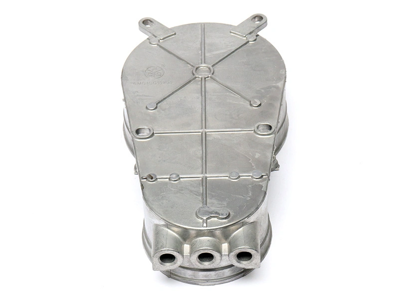
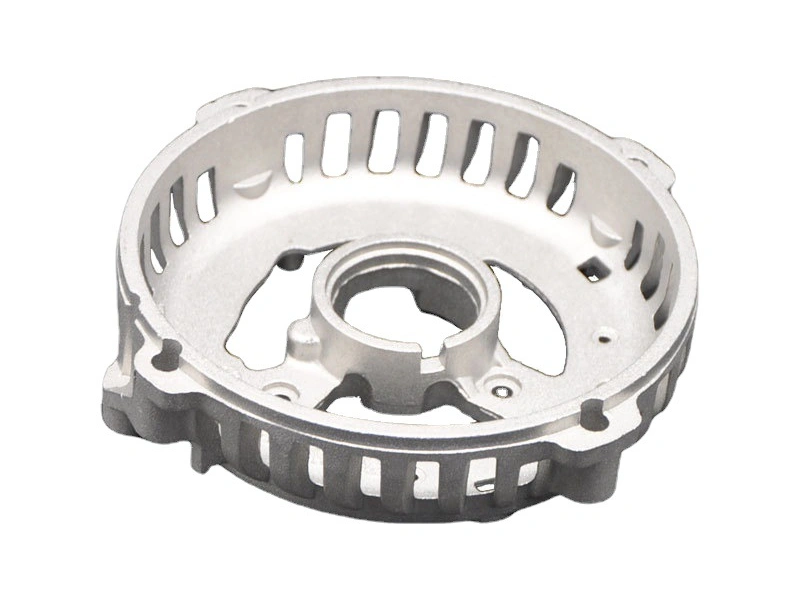
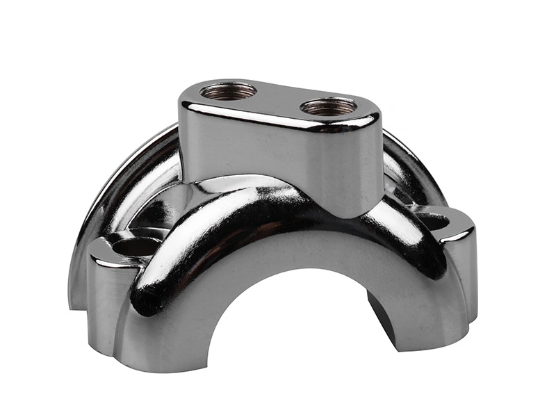
Enhancing Robotics & Automation: Die Casting for High-Strength, Lightweight Machine Components
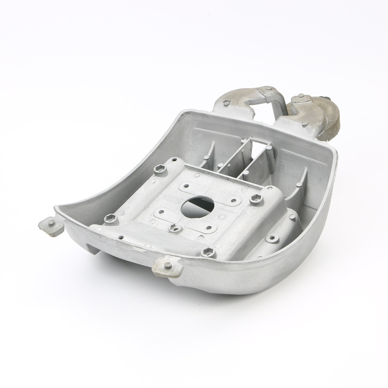 Die casting can improve robotic and automation hardware when one controlled aluminum or zinc component integrates load-carrying geometry, motor or gearbox support, sensor locations, thermal paths, shielding, cable routes, and assembly datums at a justified moving mass and production cost. It is commonly screened for actuator and gearbox housings, arm covers, bases, controller enclosures, vision and sensor bodies, gripper structures, mobile-robot chassis hardware, and automated-machine brackets. It does not automatically produce a stronger, lighter, faster, or more accurate machine.
The engineering decision must be made at axis or machine level. Alloy and geometry affect inertia, stiffness, natural frequency, fatigue, bearing alignment, thermal drift, sealing, electrical bonding, collision response, and service. Casting porosity, oxide films, machining breakout, tool variation, coating, joints, and assembly preload can alter those functions. Compare production-feasible alternatives under the same duty cycle and acceptance tests.
Define the automation function and failure consequence
State whether the component belongs to an industrial robot, collaborative application, Cartesian stage, delta robot, mobile platform, automated guided vehicle, conveyor, pick-and-place unit, machine-tending cell, gripper, vision station, or process machine. Record payload, reach, motion profile, duty, orientation, acceleration, emergency stop, collision, vibration, cable forces, temperature, contamination, and maintenance conditions. The word "robotic" does not establish one load spectrum.
Identify the load path from payload and process force through tool, wrist, links, joints, bearings, gearbox, base, fasteners, and machine foundation. Separate normal operation, programming, jam, impact, transport, maintenance, and foreseeable misuse. A cosmetic cover has a different evidence burden from a joint housing that retains a bearing or transfers torque.
Define failure in system terms: lost position, excessive backlash, resonance, bearing preload change, cracked mount, dropped tool, cable abrasion, coolant ingress, electrical noise, overheated drive, inaccessible stop, or unsafe motion. Connect each consequential characteristic to analysis, manufacturing controls, inspection, and a machine or robot test.
Place mass where the axis can use it
Low density can help, but location matters more than a simple component weight percentage. Mass near a distal wrist or fast-moving axis contributes more rotational inertia than equal mass near the base. The control result depends on motor torque, gear ratio, brake, structure, payload, path, acceleration, and tuning. Use the mechanism model to convert a feasible finished casting into axis inertia and energy, not density alone.
Part consolidation can remove covers, brackets, fasteners, welds, thermal spreaders, and alignment fixtures. It may also add ribs, casting walls, bosses, inserts, machining stock, coatings, and local reinforcement. Compare finished assemblies at equal stiffness, strength, fatigue, sealing, service, and safety functions. A lighter casting that requires a heavier motor or thicker joint elsewhere is not a system improvement.
Mass distribution also affects balance and gravity compensation. For collaborative and mobile equipment, contact behavior, stopping, stability, battery duty, and manual handling may be influenced. Those effects require the system designer's calculations and tests. A casting supplier should provide actual mass, center-of-mass information where requested, and controlled geometry, not promise a cycle-time or payload increase.
Design for stiffness and dynamic response
Motion accuracy under load depends on compliance across the entire chain. Bearings, gearbox, fasteners, joints, link sections, casting walls, mounts, floor, and thermal conditions all contribute. Tensile strength does not predict stiffness; elastic modulus, geometry, interface contact, and boundary conditions dominate small elastic deflection. Place ribs and sections around real load paths and preserve access for casting, trim, machining, assembly, and inspection.
Natural frequencies and mode shapes matter when servo excitation, gear mesh, process forces, mobile travel, or external machinery can drive resonance. A rib can raise one mode and create a local stress concentration or casting hot spot. Correlate finite-element models with representative material condition, joint stiffness, assembly preload, and physical modal or vibration tests where risk justifies it.
Lightweight optimization must include draft, fill, venting, ejectors, slides, tool steel, machining stock, and accepted discontinuity zones. A topology-optimized shell that cannot fill consistently or places oxide films across a fatigue path is not production ready. Iterate casting simulation and structural/dynamic analysis around the same geometry and process assumptions.
Choose alloy and casting route together
Aluminum die casting is often screened for motor, actuator, gearbox, controller, arm, base, and sensor housings where low density, integrated geometry, heat spreading, and shielding are useful. A380, ADC12/A383, A360, A413, AlSi12, structural HPDC families, and AlSi10Mg-type names do not describe one process or delivered condition. Select exact chemistry, route, heat treatment if any, section, and property basis.
Zinc die casting can fit compact sensor bodies, latches, encoder hardware, control components, gears, and small mechanisms where detail, wear interface, finish, and controlled small geometry outweigh minimum mass. Its density and temperature-dependent behavior need system review. Zamak 3, Zamak 5, ZA families, and other zinc alloys are not interchangeable.
Copper alloys, steel, magnesium, polymers, wrought aluminum, forgings, extrusions, and hybrid structures may serve local electrical, wear, stiffness, temperature, fatigue, or mass functions better. A machined copper conductor or forged shaft can be integrated into a cast housing. Review retention, galvanic contact, differential expansion, insulation, lubrication, particles, and service before choosing a hybrid.
Control casting integrity by functional zone
Gas porosity, shrinkage, oxide films, cold shuts, cracks, flash, inclusions, and tool damage do not have equal consequences everywhere. Mark zones around bearing seats, fasteners, thin load paths, seal lands, deep machining, grounding pads, pressure boundaries, and fatigue hot spots. Define the discontinuity model and evidence appropriate to each function rather than imposing one vague porosity statement over the whole part.
Gate, overflow, vent, vacuum where used, die thermal control, shot profile, transfer, spray, cooling, ejection, and interruptions influence integrity. Process monitoring provides useful context but cannot directly prove every internal condition. Combine controlled parameters with representative destructive examination, radiography or other NDE where suitable, machining observations, leak or pressure tests, and component load evidence.
Coupons and published values require context. Separately cast bars may not represent a thin rib, heavy bearing node, gate region, machined surface, or oxide film. If strength or fatigue data support design, identify alloy, route, condition, section, specimen location, orientation, surface, temperature, and method. Correlate high-consequence models with production-representative components.
Build motion accuracy from datums and interfaces
A die casting does not "ensure" motion accuracy by itself. Encoder position, bearing alignment, gear mesh, backlash, rail straightness, sensor pose, and end-effector repeatability depend on datum architecture, machining, assembly, preload, temperature, controls, calibration, and wear. Assign tolerances from the mechanism error budget and verify them at the state in which the machine operates.
Use as-cast features for noncritical locations where capability supports the stack. Apply CNC post-machining to bearing bores, seal lands, motor pilots, gear centers, rail mounts, encoder seats, and related datums when casting alone is insufficient. Plan fixture location, clamping, stock, porosity breakout, residual stress, tool access, burrs, cleaning, and final measurement together.
Study production by cavity and tool state. Correlate CMM, scan, gauges, surface definitions, filters, support, and temperature between supplier and buyer. Then test the assembled axis for backlash, friction, torque, runout, alignment, calibration residual, repeatability, path behavior, vibration, and thermal drift as applicable. Component conformance is necessary but does not replace machine performance.
Manage motor, gearbox, and bearing interfaces
Motor and reducer interfaces combine torque, radial and axial loads, heat, vibration, lubricant, seals, electrical bonding, and precision. Define bearing fits and shoulders from bearing arrangement, load, temperature, material, housing stiffness, assembly method, and service. A generic press fit can distort a thin cast bore or change preload.
Gear housings need center-distance and axis controls, but housing deflection, bearing clearance, shaft behavior, gear quality, lubrication, and temperature influence contact pattern and backlash. Inspect critical geometry and verify assembled mesh under representative load. Machining a bore accurately does not prove that the structure holds alignment during acceleration.
Threaded fasteners and inserts require engagement, seating, preload, relaxation, repeated service, and local casting-integrity review. Steel hardware in aluminum or zinc adds galvanic and thermal-expansion questions. Define torque method, lubricant, locking, washers, repair, and allowable reuse. Validate joints in actual cast sections rather than relying on nominal bulk strength.
Design thermal paths around real losses
Motors, drives, brakes, power electronics, sensors, lighting, batteries, and process equipment create steady and transient heat. A casting can integrate fins, spreaders, coolant passages, fan mounts, and interfaces, but bulk conductivity is only one resistance. Contact flatness, interface material, preload, coating, wall geometry, airflow, coolant, contamination, and neighboring heat sources determine component temperature.
Define loss maps and duty, ambient and enclosure conditions, allowable winding/bearing/electronic temperatures, coolant or airflow, pressure drop, noise, service, and failure modes. Model the complete path and validate production-representative assemblies with known boundary conditions. A cool housing surface does not prove that a motor winding or semiconductor junction is within limit.
Thermal gradients can shift precision datums and bearing centers even when average temperature is acceptable. Warm-up, asymmetric drives, fan cycles, washdown, and changing payload can produce transient drift. Measure temperature and motion together. If control compensation is used, validate sensors, models, software version, aging, and upset conditions.
Design electrical bonding, EMI, and cable protection
Metal housings can support protective bonding, functional grounding, electromagnetic shielding, heat spreading, and electrostatic control. Performance depends on seams, covers, apertures, connector panels, cable glands, fasteners, gaskets, oxide, paint, masked pads, contact force, frequency, and corrosion. A material conductivity value cannot approve the assembled enclosure.
Mark grounding and thermal contacts on controlled drawings. Coating and oxidation can increase resistance; machining or masking can expose substrate and corrosion. Verify contact resistance, continuity, shielding, emissions, immunity, and environmental durability at assembly level according to the system plan. Keep signal, motor, brake, encoder, network, and power paths separated where architecture requires it.
Cable routes need bend radius, strain relief, dynamic flex, abrasion, edge protection, connector access, coolant exposure, and service consideration. Integrated casting channels can protect cables but can also trap contaminants or make replacement difficult. Remove flash and burr hazards and validate the full motion envelope.
Qualify temperature, corrosion, and ingress
High-temperature suitability depends on peak and sustained temperature, gradients, dwell, cycles, load, creep, fatigue, aging, lubrication, seals, electronics, coating, and dimensional need. Corrosion depends on humidity, washdown, coolants, cleaners, salt, process chemicals, metal couples, electrical potential, crevices, drainage, scratches, and time. Do not publish one maximum temperature or coating life for all die castings.
Ingress protection is an assembled-enclosure result. The casting contributes walls, flanges, groove geometry, porosity control, machined ports, drainage, and fastener support, while seals, glands, covers, torque, surface, vents, and assembly complete the boundary. Validate specified dust and water exposures on production assemblies after relevant aging, vibration, temperature cycling, and service.
Finishes should match the mechanism. Conversion coating, anodizing where alloy and function permit, paint, powder coating, plating, and sealers can support corrosion, wear, appearance, electrical, or cleaning needs. Qualify the complete substrate and layer stack, including pretreatment, edges, pores, masks, rack points, cure, damage, repair, and final dimensions.
Select the route with a system decision table
Automation need | Route to screen | Evidence before selection |
|---|---|---|
Integrated motor, sensor, thermal and mounting housing | Aluminum die casting plus selective machining | Inertia/stiffness model, DFM, integrity, datums, thermal and axis tests |
Small detailed control or mechanism hardware | Zinc die casting | Mass, wear, aging, finish, environment and assembly evidence |
Low demand, changing geometry or wrought material | CNC machining or fabrication | Stock condition, fixtures, burr/cleaning, precision, change and total cost |
Highly loaded shaft, arm or compact load member | Forging, extrusion or machining | Material form, heat treatment, fatigue, joints and component load tests |
Mixed electrical, wear and structural functions | Hybrid casting with inserts/components | Retention, galvanic, thermal, tolerance, insulation, fatigue and service |
Compare complete production chains. Include tooling, fixtures, machine capacity, conforming yield, machining, finish, assembly, inspection, validation, maintenance, design revisions, spare tools, service parts, transfer, and downtime. High demand can justify dedicated mass-production tooling, but demand alone does not prove die casting is the lower-risk route.
A large integrated casting can reduce assembly stations while concentrating supply and scrap risk. CNC or fabrication may carry higher recurring work but allow distributed equipment and easier revisions. Model credible demand, yield, change, and disruption scenarios rather than one optimistic annual quantity.
Control tooling, cavities, and production change
Tool design must align parting, slides, ejectors, gates, overflows, vents, cooling, inserts, trim, handling, and measurement with functional zones. Tool steel and local inserts are selected from thermal, wear, checking, soldering, erosion, repair, and cost conditions. Tool life cannot be promised from alloy family alone; geometry, machine, process, maintenance, acceptance, and repair history determine useful life.
Identify each cavity and critical tool insert in records. Monitor relevant dimensions, flash, surface, process state, and maintenance trends. Establish warm-up and restart controls. A repaired gate, bearing-forming insert, slide, cooling circuit, or datum surface can require new layouts and functional evidence even when the drawing revision is unchanged.
Define notification triggers for material source and chemistry, return policy, machine, tool, cavity, gate, vent, vacuum, process limits, heat treatment, machining fixture, coating, cleaner, inspection program, software, site, and sub-tier. The robot or machine manufacturer decides the affected verification and validation before approval.
Connect component evidence to machine safety
Robot and machinery safety belongs to the complete application. Applicable standards, regulations, risk assessment, safeguarding, control system, installation, end effector, payload, speed, workspace, human interaction, and validation determine the result. A die casting cannot be called collaborative, safe, or compliant in isolation.
Component controls can support risk reduction: retaining a brake or gearbox, maintaining guard and sensor positions, protecting cables, preserving grounding, containing lubricant, or resisting foreseeable loads. Identify safety-related characteristics and change controls on authorized documents. Verification should include the component and assembled behavior needed by the risk assessment.
For contact-capable applications, mass, inertia, geometry, edges, padding, speed, force/torque sensing, controls, stopping, payload, and body-region exposure can interact. Do not convert an aluminum weight reduction into a universal safe-contact claim. The system integrator must validate the actual robot, tool, task, settings, and workplace.
Validate prototypes with their route visible
A machined billet, polymer print, or temporary fabrication can answer packaging, kinematics, sensor field, cable routing, user access, control, and early thermal questions. It cannot prove die fill, casting discontinuities, tool-derived dimensions, production surface, cavity variation, or casting fatigue. Record material form and manufacturing route in every prototype conclusion.
Use production-intent castings for final integrity, motion, thermal, electrical, environmental, durability, and safety-related evidence. Include the intended alloy, tool, cavities, machining, finish, inserts, assembly, firmware/control configuration, lubrication, cables, and payload. Test across relevant temperature, duty, wear, maintenance, and upset conditions.
Calibration can compensate repeatable geometric error, but it cannot make an unstable structure, loose joint, drifting bearing fit, or changing thermal path acceptable. Separate calibrated accuracy from mechanical stability. Recheck calibration and functional performance after tool/process changes that can affect the model.
Prepare an RFQ for robotic die-cast components
Provide controlled models and drawings, machine type, component function, axis location, payload and process forces, motion and duty, acceleration and emergency loads, stiffness and modal targets, fatigue life definition, temperature and heat losses, electrical/EMC needs, environment, ingress, lubricant and chemicals, interfaces, special characteristics, safety consequences, demand, lifecycle, finish, inspection, tests, traceability, capacity, service, and change requirements.
The supplier should return exact alloy and route, mass and assumptions, DFM exceptions, structural/integrity zones, gate/vent/cavity concept, machining and datum plan, surface stack, inspection, samples, sub-tiers, tool maintenance and spares, capacity, continuity, validation support, traceability, change triggers, and open risks. Use engineering review to resolve conflicts before tooling.
A high-strength, lightweight robotic component is not proven by a catalog tensile value or a thin wall. It is proven when the finished production part carries its real loads with controlled deflection and fatigue, preserves motion interfaces through temperature and wear, supports electrical and environmental functions, and remains manufacturable, inspectable, serviceable, and controlled over the machine lifecycle.
FAQs
What are the most suitable alloys for die cast robotic components?
How does die casting ensure tight tolerances for motion-critical parts?
Can die cast parts be used in high-temperature or corrosive environments?
What finishing methods improve the performance of robotic housings?
How does die casting compare to CNC machining in automation hardware?