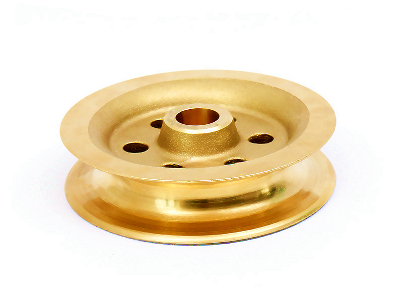
Custom brass casting can be a sensible route for a transmission wheel, gear blank, hub or indexing component when the copper alloy is available in the required cast product form and the design benefits from near-net geometry, damping, machinability or corrosion behavior. It is not an automatic route for a finished precision gear. Tooth accuracy, bore-to-pitch concentricity, runout, wear and torque transfer usually require a planned combination of casting, machining, deburring, lubrication and assembly validation.
The sourcing decision therefore starts with the mechanism, not with a generic brass property table. A lightly loaded actuator wheel, a sliding worm-wheel pair, a keyed timing hub and a shock-loaded conveyor sprocket expose different failure modes. The drawing, mating member, duty cycle and inspection definition must show which features can remain cast and which need cutting from a common datum. That distinction is the basis of a defensible copper-alloy casting proposal.
State what the wheel actually does. Gears transmit torque through conjugate tooth contact. Sprockets engage a chain and are governed by chain geometry. Pulleys transfer force through a belt and depend on groove form, wrap and traction. Indexing wheels locate positions through pins, slots or detents. Friction wheels rely on surface traction rather than tooth contact. Calling all of them transmission wheels hides the requirement that controls manufacturing.
Record input torque and speed, start-stop frequency, reversing, shock, dwell, target life, temperature, lubricant, contamination, shaft support and allowable noise. Include radial, axial and overturning loads from the complete drive. A nominal motor torque alone does not capture a jam, emergency stop, belt preload or an overhung wheel. Buyers should also define the consequence of slip, backlash, tooth damage or hub loosening because that consequence sets the verification depth.
A cast blank with a web, hub and machining allowance is a different product from a wheel with cast-to-size teeth. Near-net casting can consolidate spokes, stops, sensor flags, counterbores or attachment features, while hobbing, shaping, broaching or CNC cutting establishes the functional tooth and bore geometry. This hybrid route is often easier to qualify because the teeth and bore can be generated from controlled datums after casting distortion is present.
Cast teeth may be considered for coarse, low-load or positioning functions when draft, parting line, flash control, shrinkage and tool wear fit the acceptance criteria. Fine-pitch, quiet, high-contact-ratio or heavily loaded teeth deserve particular caution. A visually complete tooth is not evidence of profile, lead, pitch or contact performance. Require a production-intent measurement and loaded mesh test before treating near-net teeth as finished.
Component concept | Route worth comparing | Main risk | Approval evidence |
|---|---|---|---|
Coarse indexing wheel with integrated stops | Near-net casting with local bore and face machining | Slot spacing, flash and bore-to-index relationship | Index error report and mechanism cycle test |
Precision spur gear with hub and web | Cast blank followed by bore and tooth generation | Datum transfer, stock variation and tooth-runout stack | Gear metrology from the functional bore plus mesh test |
Sliding worm wheel | Qualified copper-alloy blank with machined tooth form | Material pairing, lubrication, contact temperature and wear | Representative pair tested under load, speed and lubricant |
Thin lightweight timing pulley | Aluminum casting, extrusion or machining comparison | Brass mass may add inertia without useful benefit | Acceleration, balance, belt tracking and total-cost comparison |
Shock-loaded pinion or small drive gear | Machined or formed steel route comparison | Tooth-root fatigue and impact may dominate machinability | Duty-based stress analysis and overload/endurance test |
Die casting is strongest where integration and repeat volume offset tooling and where the geometry can fill, vent, eject and be inspected. A low-volume gear that is mostly machined surfaces may be better made directly from stock. The low-volume route should remain open until prototype evidence shows which design features are worth tooling.
Brass is a family, not one material. Copper, zinc, silicon, tin, lead and other additions change filling, hot tearing, strength, machinability, corrosion and tribological behavior. More importantly, a designation familiar as bar, plate or forging stock is not automatically available or suitable as pressure-die-casting feedstock. Confirm the governing material specification, chemistry, casting process, supplied condition and any heat or surface treatment.
A page describing copper and brass alloys is useful for an initial discussion, but the purchase order needs an exact product-form proposal. For example, a free-machining grade may make bore, keyway and tooth cutting attractive, yet its lead content or casting route may conflict with the application. A silicon brass candidate may support a cast route, but its actual machinability, shrinkage and wear behavior must be verified in the proposed condition.
Do not copy strength, hardness or machinability ratings from wrought temper data into a casting release. Ask whether each number is a specification minimum, handbook typical, supplier certificate or test from representative geometry. If material compliance or restricted substances matter, name the applicable market and part scope. A commercial alloy label alone is not a compliance statement.
Torque enters through a shaft fit, key, spline, pin, clamp or insert and leaves through teeth, belt, chain or friction contact. Trace that path on the CAD model. Hub splitting, keyway bearing, web bending and local porosity can control failure even when the tooth calculation appears comfortable. Include root fillets, hub length, key-end geometry, press-fit stress and the effect of machining stock removal.
Evaluate steady and alternating tooth load, reversal, impact and overload separately. A wheel that survives nominal torque may loosen under repeated reversal or crack after a jam. For an overhung wheel, shaft deflection and bearing clearance change tooth contact. The component supplier needs the shaft arrangement and mating-wheel position, not only a standalone wheel drawing.
Wear belongs to the pair: brass against steel, polymer, another copper alloy or a coated member. Sliding/rolling ratio, contact stress, speed, alignment, lubricant viscosity, additives, temperature, abrasive particles and surface topography interact. Brass should not be described as universally self-lubricating. Some copper-alloy pairs provide favorable anti-galling behavior, but a loaded gear still needs a defined lubrication and contamination plan.
For worm gearing, sliding and heat generation can dominate. For spur gears, tooth form, lead, pitch error and shaft deflection affect load sharing. A sprocket sees pin or roller articulation and contamination. An indexing wheel may fail by edge peening rather than classical gear wear. Specify the actual mate, lubricant application method, relubrication interval and acceptable wear or backlash growth.
The functional axis usually comes from a finished bore, bearing seat or shaft interface. Gear pitch, tooth runout, face runout and hub features should reference that axis in a coherent datum scheme. Referencing the cast outer diameter for convenience can create an inspection result that does not predict assembled mesh. If a face locates the wheel axially, define it as part of the functional coordinate system.
Plan how the first machining setup locates the casting and how later setups preserve the relationship between bore, face, keyway and teeth. Cast pads may be added as temporary locating features, but their stability and removal need control. When teeth are machined before the final bore, explain how the bore will be related to the gear datum. There is no inspection shortcut that repairs an incoherent process sequence.
Machining allowance must cover draft, parting-line offset, shrinkage variation, local distortion and the datum setup without hiding unacceptable casting conditions. Excess stock increases cutting time and may open subsurface porosity. Too little stock creates interrupted cleanup on a seal, bearing seat or tooth blank. Mark every machined surface and state whether full cleanup is required.
Keep gates, overflows, ejector marks and flash away from the gear datum and high-contact surfaces. A gate feeding the rim may support fill but leave removal or balance work. A gate feeding the hub may affect the bore zone. DFM should show how metal reaches the rim and web, where air exits, how the part ejects and which regions receive machining. Tool design and die construction are part of the transmission risk review, not merely a tooling quotation.
Do not place one linear tolerance on gear pitch, bore size, tooth profile, runout and backlash. They are different characteristics. A gear quality grade uses defined measurement parameters and methods; it is not interchangeable with a plus/minus pitch-circle dimension. Bore fit depends on the shaft system and assembly method. Runout requires a datum and measurement direction. Backlash is an assembled result involving both gears and center distance.
Divide the drawing into as-cast, machined and assembled requirements. Keep cast tolerances appropriate to the geometry and route, then machine only the features that control fit or motion. The answer to an achievable tolerance question comes after part size, wall transitions, alloy, cavity layout, datum accessibility, machining sequence and gauge method are known. Capability should be demonstrated on production-intent parts, by cavity where applicable.
Characteristic | Functional question | Measurement approach | Release record |
|---|---|---|---|
Bore size and form | Will the shaft fit and retain as intended? | Agreed bore gauge or form-capable measurement after final operation | Size, roundness/form where relevant and gauge method |
Radial tooth runout | Will mesh depth vary as the wheel turns? | Gear measurement referenced to the functional bore axis | Defined parameter, datum and result by sample/cavity |
Profile, lead and pitch | Will load distribute over the intended flank? | Gear analyzer or agreed analytical/composite inspection | Named standard, grade/limits and report format |
Face runout | Will axial location or belt/chain tracking vary? | Rotation about the functional axis against the locating face | Datum setup and total indicated variation |
Backlash/contact | Does the assembled pair carry load correctly? | Master mate or actual assembly at controlled center distance | Fixture, torque, temperature and acceptance evidence |
Balance or mass eccentricity | Will speed create vibration or bearing load? | Application-appropriate balance or run test | Speed, mounting method and residual criterion |
Inspection resolution and uncertainty must be suitable for the limit. Use available inspection equipment only where the method answers the functional question. A CMM may locate features, while dedicated gear metrology better resolves tooth parameters. A hand check that cannot distinguish part variation from fixture variation should not support a tight capability claim.
At low speed, geometric runout and contact may matter more than dynamic balance. As speed rises, asymmetric spokes, gates, keyways, inserts, local porosity and machining removal can create vibration. Define the operating-speed range, acceleration, mounting orientation and bearing sensitivity before adding a generic balance callout. The finished wheel, not an unmachined casting, is the relevant object.
If material will be removed for balance, reserve accessible correction zones away from stressed roots and functional surfaces. Cavity identity can help trace recurring eccentricity to tool or trim conditions. A balance operation cannot correct tooth runout caused by bore misalignment, and a precise bore cannot correct an uneven mass distribution. Treat these as separate controls.
Deburring and controlled edge treatment may be more valuable than a decorative coating. Remove flash or burrs that interfere with mesh, but do not round tooth tips, edges or reference faces without an approved profile. Tumbling can reach many surfaces at once, yet it can also change small teeth and trap media. Evaluate a post-process on actual geometry.
Nickel or another coating should not be specified simply as wear protection. Coating thickness changes tooth thickness, bore fit and backlash; pretreatment can attack or embrittle an unsuitable substrate; adhesion and cracking depend on contact stress and bending. Masking creates edge transitions. For many gear sets, controlled cutting, flank texture, correct mate and lubricant are the primary wear controls. Add a coating only after representative pair testing shows a benefit without dimensional or fatigue damage.
A machined-from-stock prototype can answer packaging, bore fit, tooth geometry and basic mechanism questions quickly, but it does not validate casting fill, porosity, distortion or production machining stock. A soft-route casting may explore material and geometry while differing from the thermal and filling conditions of the production tool. A production-intent cavity is needed to establish the final casting-to-machining relationship.
Create a question matrix for each prototype. Fit checks may use substitute material. Noise and wear tests need the intended mate, lubricant, surface and material condition. Tool qualification needs cast parts from the intended process. The principles of functional prototype testing are useful only when the report states which production risks remain open.
Bench inspection should be followed by assembly evidence at representative center distance, alignment, torque, speed, lubricant, temperature and contamination. Run-in behavior is not the same as steady-state wear. Record backlash or torque before and after the test, inspect contact patterns and characterize debris where failure analysis matters. A no-load spin test will not validate loaded flank behavior.
Include starts, reversals, stops and overloads if the application experiences them. Monitor temperature, noise, current or torque where those signals reveal changing friction. After testing, inspect tooth flanks, roots, bore/keyway and hub. A wheel can pass gear metrology and still fail at the shaft interface; conversely, a strong hub cannot compensate for poor tooth contact.
Production controls should connect material lot, melt/process record, tool and cavity, trim, heat treatment if any, machining setup, cutter life, finish batch and final inspection. Multi-cavity production needs evidence that one cavity is not hidden by pooled results. Control plans should distinguish process-monitoring dimensions from functional gear characteristics and define reaction when drift appears.
Tool wear may alter flash, draft surfaces or near-net tooth features; cutter wear may alter finished profile or burr condition. Neither has a universal life. Establish maintenance and replacement from measured trend, defect history and mechanism performance. Before mass production, demonstrate good parts per scheduled hour through casting, machining, deburring, washing, inspection and any pair testing, not just machine cycle time.
Include material yield, tooling, trim, machining stock, tooth generation, keyway or spline cutting, deburring, cleaning, coating, inspection, balance, assembly and rejected finished-part value. A cheaper blank can become expensive if datum variation forces more stock or inspection. A higher-cost alloy may still be useful if it improves a verified machining or wear requirement, but that value should be shown in the finished system.
Compare brass with steel, aluminum, zinc, engineering polymers and machined stock using the same duty and volume. Steel may win for impact and high tooth stress. Aluminum may win for inertia. Polymer may win for quiet low-load motion. Brass may win where a compatible tribological pair, corrosion exposure, compact mass, cast integration and machining combine favorably. There is no useful material ranking without these boundaries.
Send controlled CAD and drawings, component type, module or pitch system, tooth count and form, pressure angle or mating geometry, shaft/bore/key/spline definition, functional datums, center distance, backlash target and mate details. Add torque/speed/time history, starts and reversals, shock or jam cases, life, temperature, lubricant, contamination, corrosion, noise, inertia, balance and assembly method.
State exact material specification/product form or permit documented alternatives. Mark cast and machined surfaces, required cleanup, coating/masking, edge conditions, inspection parameters, sampling, capability expectations, prototype quantities and annual demand. Request separate price and schedule for blank, machining, tooth generation, finish, inspection and validation. Ask for a process flow showing how the functional bore, face and tooth coordinate system will be preserved.
Choose custom brass casting for transmission wheel hardware when a verified cast alloy and near-net design reduce manufacturing or assembly burden while the finished teeth, bore, runout, balance and wear can be proven under the real duty. Treat a cast gear blank and a finished precision gear as different approval stages. Reject proposals that promise one tolerance, gear grade, coating life, tool life or delivery time without the geometry, datum scheme, mating pair and test conditions.
A strong release connects four records: route-feasible DFM, exact material and condition, dimensional evidence from the functional axis, and transmission-pair testing under load. That chain is what turns a brass casting into reliable mechanical hardware.
What brass alloys are best for precision gear and wheel die casting?
How does brass compare to steel or aluminum for small mechanical transmissions?
What tolerances can be achieved for gear pitch and bore alignment?
What surface finishes are recommended for reducing gear wear?
How fast can prototypes be delivered for custom gear projects?