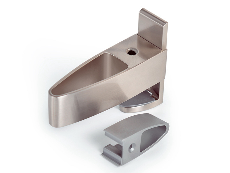
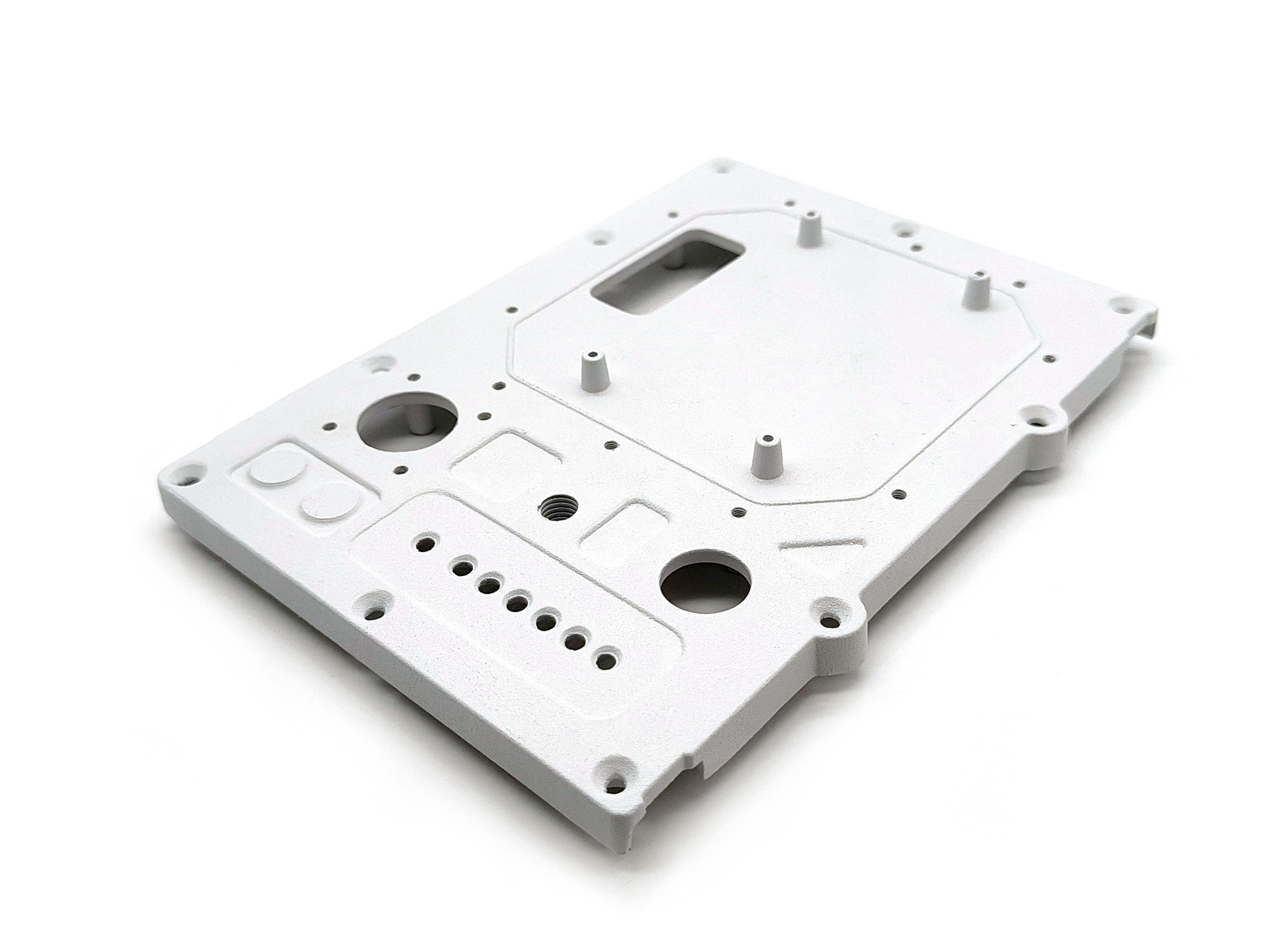
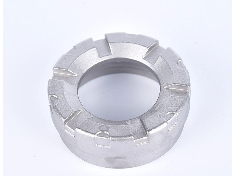
Zinc die casting can be cost-effective for compact machinery housings, covers, brackets, guides, latch bodies, actuator carriers, sensor mounts and control hardware when complex near-net geometry and repeat volume replace several fabricated or machined pieces. It is not a default choice for gear teeth, bearing journals, shafts, high-temperature structures, severe impact members or pressure boundaries. Those duties may require steel, stainless steel, aluminum, bronze, polymers or purpose-selected inserts.
The economic decision must use accepted finished assemblies and machine consequences. Tooling, casting yield, machining, coating, assembly, inspection, inventory, maintenance, field replacement and downtime can outweigh raw metal price. A low-cost casting that loses alignment, corrodes at a fastener or cracks a loaded lug is not cost-effective.
Name the function before the material: enclosure, alignment carrier, static bracket, motion guide, latch, handle, sensor body, connector shell, lubrication cover, counterweight or cosmetic guard. Map static load, shock, vibration, fatigue, wear, temperature, moisture, chemicals, UV, dust and expected service operations.
Identify failure consequence. A removable inspection cover can tolerate different deformation from a motor bearing carrier. A position-sensor bracket may carry little force yet cause costly machine error if it creeps or shifts. Use the operating and maintenance team to define credible loads and environments.
Separate structure from wear and sealing interfaces. Zamak can carry a steel pin, bushing, thread insert or bearing selected for local duty. Hybrid architecture often avoids asking the casting to behave like hardened steel while retaining integrated geometry.
Component condition | Potential zinc value | Required challenge |
|---|---|---|
Complex compact housing | Integrated bosses, ribs, passages and mounting features | Temperature, sealing, grounding, impact and machining strategy |
Static alignment bracket | Repeatable datums and consolidated fasteners | Long-term load, flatness, vibration and fastener retention |
Latch or actuator carrier | Near-net pivots, stops and spring seats | Cycle load, wear, shock, lubrication and replaceable interfaces |
Outdoor control hardware | Compact conductive enclosure and detailed geometry | Complete coating, drainage, dissimilar metal and conditioned function |
Gear tooth, bearing or shaft surface | Possible surrounding carrier only | Use a purpose-selected insert or another material for the working surface |
Hot or pressure-retaining part | Conditional and often poor fit | Temperature-time behavior, pressure code, leakage and safer alternatives |
This screen should create comparison concepts, not approve Zamak. Every claimed benefit needs a drawing, operating condition and verification method.
Zamak 3 is a useful baseline for many dimensionally controlled housings and general components. Zamak 5 may be evaluated where loaded lugs, pivots or wear-adjacent features need a different strength and hardness balance. Zamak 2 can enter a specific comparison, but its property profile and dimensional behavior must be matched to the duty and service period. No grade is automatically best for a dynamic assembly.
Zamak alloy selection should use controlled specifications, exact casting condition and part tests. Check fatigue, impact, sustained load, wear, temperature and environment according to the component. Published material data cannot represent a pore, flow join, machined edge or assembled press fit.
Control alloy identity, melt contamination and internal returns. Keep cavity and lot linkage through machining and finishing. When field performance matters, investigation needs to connect a failed part to its actual process history.
Integrated complexity only saves money when it remains manufacturable and inspectable. Use smooth section transitions, practical radii, supported bosses and ribs aligned with load. Avoid thin cantilevers, abrupt lug roots and trapped steel around slides. Keep parting, ejectors and flow joins away from the highest-stress regions when possible.
Map fastener preload, bearing reaction, belt or chain force, cable pull, motor torque, actuator impact and service-tool loads into the machine frame. Consider misuse such as overtightening, prying a cover or lifting by a handle. A strong nominal alloy cannot correct a poor load path.
Zinc casting DFM should coordinate wall transitions, draft, threads, ribs, slides, gates, vents and ejection. If a feature cannot be verified or maintained, part consolidation may increase lifecycle cost.
Industrial machinery may expose parts to motor heat, oil, steam lines, heaters, outdoor sun or repeated thermal cycling. Define continuous, intermittent, startup, shutdown and fault temperatures at the component. Mechanical behavior, dimensions, coatings, seals and fastener preload can change with temperature and time.
Do not approve a Zamak bracket from a room-temperature pull test if it supports sustained load near a heat source. Evaluate creep or relaxation risk, differential expansion with steel or aluminum, and loss of alignment after conditioning. Move the part, reduce temperature, change geometry or use another material when margin is uncertain.
Thermal expansion can also affect bearing fits, seals and sensor gaps. Validate the complete tolerance stack over the defined machine cycle, including coating and insert materials.
A Zamak carrier can support motion, but sliding or rolling contact needs an explicit tribology decision. Define load, speed, motion amplitude, duty cycle, contamination, lubricant, temperature and acceptable backlash. Compare direct alloy contact with bushings, hardened pins, rolling bearings, polymer liners or replaceable wear plates.
Keep flash, parting lines and coating buildup away from motion paths. Provide lubricant access and retention without creating dirt traps. Check galvanic and chemical compatibility among Zamak, steel, bronze, grease and cleaning agents.
Test the assembled mechanism, not isolated hardness. Measure force, clearance, noise, temperature and wear debris over the relevant duty. Establish replacement criteria for consumable inserts before the housing is damaged.
Large spans, asymmetric sections, ejection, trim, machining clamps and coating can distort a casting. Define functional datums, free-state or restrained measurement, support points, temperature, timing and assembly condition. A flatness number without a measurement setup is ambiguous.
Machine only the features whose function requires it, such as bearing bores, seal lands, connector openings and alignment datums. Plan stock, fixture force, cutting sequence, burr removal and porosity response before tool release. Cast and machined datum chains should not fight each other.
Coordinating CNC machining with zinc casting reduces unnecessary stock and exposes whether a critical surface intersects a likely pore zone. Use production-intent fixtures and gauge methods during trials.
Do not infer pressure capability from a dense-looking casting. Sealing depends on wall architecture, porosity routes, machined openings, gasket compression, fastener layout, distortion, surface finish and test condition. Identify whether fluid is lubricant, coolant, water, air, vacuum or an aggressive chemical.
Use risk-appropriate leak or pressure tests on the complete configuration. If a pore connects after machining, define containment and process action rather than relying on coating to hide it. Critical pressure parts may require another process or material selected to the applicable design requirements.
Provide drainage and avoid stagnant pockets for outdoor or washdown machinery. Check seal function after vibration, temperature cycling, fastener access and corrosion exposure.
Zamak machinery parts may use controlled conversion or pretreatment, plating, paint, powder coating or clear protection, with mechanical preparation where justified. Anodizing is not a standard surface treatment for a Zamak substrate. Select the layer system for moisture, chemicals, UV, abrasion, contact, grounding and appearance.
Zinc surface-finishing options should be specified as a complete stack. Define preparation, edges, recesses, rack or mask witness, thickness locations, adhesion, color, repair and packaging. Flat coupons do not represent holes, threads, fastener seats and sharp edges.
Keep coating away from bearing fits, grounding contacts and seal lands where required. Verify the affected assembly dimensions after finish. If field scratches expose base metal, define inspection and replacement or repair criteria.
Vibration failure can begin at a resonant bracket, loose fastener, wire harness, heavy connector or unsupported PCB rather than in the alloy. Define spectra or machine conditions, mounting, preload and combined temperature/environment. Use locking strategy and inserts appropriate to repeated service.
Outdoor durability depends on drainage, layer integrity, dissimilar-metal joints, UV, condensation, salts, pollutants and damage. Condition the final assembly, then check corrosion, grounding, fastener removal, seal, latch force and alignment. Do not convert a salt-spray duration directly into field life.
Zinc use in vibration and outdoor environments is conditional on this design and validation evidence, not just the alloy grade. The release record should identify the tested mounting, finish, seals, fasteners and environmental sequence.
Tool concept should reflect annual demand, cavity balance, slides, inserts, hot spots, ejection, trim, critical steel and measurement access. A low initial tool price may create high flash, manual rework, weak cooling or difficult maintenance. Compare expected accepted output and ownership of spare or replacement inserts.
Tooling affects cost and production stability through much more than die life. Define approval gates for tool design, steel release, trial, correction, finished samples and pilot production. The project schedule must be built from the actual geometry and approvals, not a generic number of weeks.
Record tool and cavity revisions. When a slide, gate, vent or insert changes, review connected dimensions, surface, load and process evidence before releasing repeat production.
Create a requirement-to-test matrix for load, fatigue, impact, vibration, temperature, wear, corrosion, ingress, grounding, noise, dimensions, fastener retention and service. Apply only relevant tests, but combine conditions where real duty combines them. A coated bracket may pass corrosion and vibration separately yet fail when corrosion reduces a grounding contact under vibration.
Use production-intent parts from every cavity with actual machining, finish, inserts, fasteners, lubrication and mating components. Include dimensional and process extremes. Trace failures to their origin and update design, tool, process or acceptance accordingly.
Functional testing for zinc assemblies should verify machine-level outcomes such as alignment, motion, seal, force and retained fasteners after conditioning.
Decide how operators install the part, how technicians reach fasteners, and what must be removed for inspection or replacement. Provide tool access, lead-in, connector clearance and safe lifting or handling points. A consolidated casting can reduce assembly count while making one inexpensive wear item impossible to service; that is usually poor lifecycle economics.
Choose inserts and fasteners from the required access frequency. A thread used once at controlled torque differs from a cover opened every maintenance interval. Verify cross-thread resistance, tightening sequence, clamp load, removal after corrosion exposure and debris control. Prevent screws from bottoming into a blind hole or reaching a moving or energized component.
Use error-proofing for similar covers, mirrored brackets, sensor positions and seal orientation. Define whether subassemblies are replaceable in the field or only at a repair center. Service instructions and spare-part identity should match the drawing revision and finish; an apparently interchangeable older casting can have a different clearance, coating or ground path.
Identify special characteristics from machine function: bearing or sensor location, seal land, loaded lug, threaded insert, ground contact and actuator stop. Connect each to a capable measurement or functional gauge and a reaction plan. Avoid measuring every CAD dimension while leaving the characteristics that control alignment or motion weakly defined.
Approve the measurement system before relying on capability statistics. CMM programs, attribute gauges, torque tools and leak fixtures need controlled revisions, calibration and repeatability appropriate to the decision. Sample by cavity and process interval; mixed results can hide a local tool or cooling problem.
Track raw casting yield separately from finished and assembled yield. A cavity that passes dimensions but repeatedly opens pores during machining or blisters after coating is not stable. Link scrap and rework to cavity, tool revision, casting interval, fixture and finish load. This evidence directs improvement and makes the quoted accepted-part cost auditable.
Industrial machines may remain in service after the original production forecast ends. Define tool storage, preservation, ownership, maintenance records, last-time buys and the process for restarting after inactivity. A replacement part must still fit older machines, but uncontrolled backward compatibility can preserve a known weakness.
Decide which tool inserts, gauges, machining fixtures and approved finish standards require spares. Qualify alternate sub-tier processes before an emergency where possible. Changes to alloy source, coating chemistry, fastener or lubricant may affect fit and field performance even when the casting drawing is unchanged.
Model inventory by machine population and failure consequence. A low-volume service lot may have high setup cost but prevent expensive downtime. Conversely, overbuying branded or revision-specific castings can create obsolete stock. Include this service strategy when comparing die casting with tool-free or lower-tooling alternatives.
Build the cost model from design work, prototype, tool and spare inserts, casting setup, alloy and shot weight, yield, trim, machining, surface finish, assembly, inspection, packaging, freight, inventory and change risk. Divide by accepted finished assemblies. Add maintenance, service labor, replacement, machine downtime and failure consequence where sourcing choices can affect them.
Die-cast cost drivers should be quoted on the same specification and forecast. A design that eliminates two brackets may justify tooling; a design that adds complex slides and manual polishing for no functional benefit may not.
Compare Zamak against machined billet, stamping/fabrication, aluminum die casting, polymer molding and hybrid routes. Use realistic revision and demand scenarios. Tool amortization over an optimistic volume can hide commercial risk.
Request a sensitivity view rather than one unit price. Show how accepted cost changes with release quantity, cavity utilization, machining time, finish yield and assembly loss. Include the cost of planned inspection and test records. A supplier should state which assumptions are quoted and which remain open until tool trials.
Estimate machine consequences separately from manufacturing conversion. Consider installation time, alignment effort, preventive maintenance, spare stocking, replacement access and the production loss caused by a failed component. The monetary value of downtime is application-specific, but omitting it can favor a fragile low-price design.
Use the model to decide where additional evidence pays. A low-consequence cover may not justify extensive endurance work, while a compact bracket that locates a production sensor may warrant more validation and service stock. Cost-effective engineering spends control effort in proportion to failure consequence.
Provide CAD and drawings, component function, load paths, temperature/time, vibration/shock, wear and lubrication, environment, fluid/pressure boundary, mating materials, datum and machining plan, finish, fasteners/inserts, assembly, validation, inspection, traceability, packaging, annual and release quantities, service life and failure consequence.
Ask suppliers to return alloy and metal-control assumptions, DFM and alternatives, gate/vent/ejection plan, tool/cavity/slide concept, porosity-sensitive areas, machining and fixture strategy, finish stack, sub-tiers, validation support, control plan, change rules, cost breakdown and exceptions.
Zinc die casting is cost-effective for a complex machinery part when the complete architecture meets its assigned duty with repeatable production evidence and a lower total accepted or lifecycle cost than credible alternatives. Complexity by itself is not the business case.