What are the best practices for designing parts with varying wall thicknesses in metal casting?
Designing cast parts with varying wall thicknesses presents a unique set of challenges in metal casting, especially regarding filling performance, solidification control, and dimensional stability. Uneven wall thickness can lead to shrinkage porosity, warping, cold shuts, and thermal stresses. Engineers should follow well-established best practices rooted in DFM (Design for Manufacturability) and metal flow simulation analysis to prevent these issues and ensure a robust, manufacturable design.
Minimize Wall Thickness Variation
Excessive variation in wall thickness creates non-uniform cooling rates, which increases the risk of internal defects. The best practice is to minimize variation within ±20–30% across the part where possible.
For aluminum alloys (e.g., A380), ideal wall thickness is 2.5–3.5 mm
For zinc alloys (e.g., Zamak 5), walls as thin as 0.6–1.5 mm are feasible due to better flow characteristics
For copper-based alloys, thicker sections of 4.0–6.0 mm may be necessary to manage flow resistance
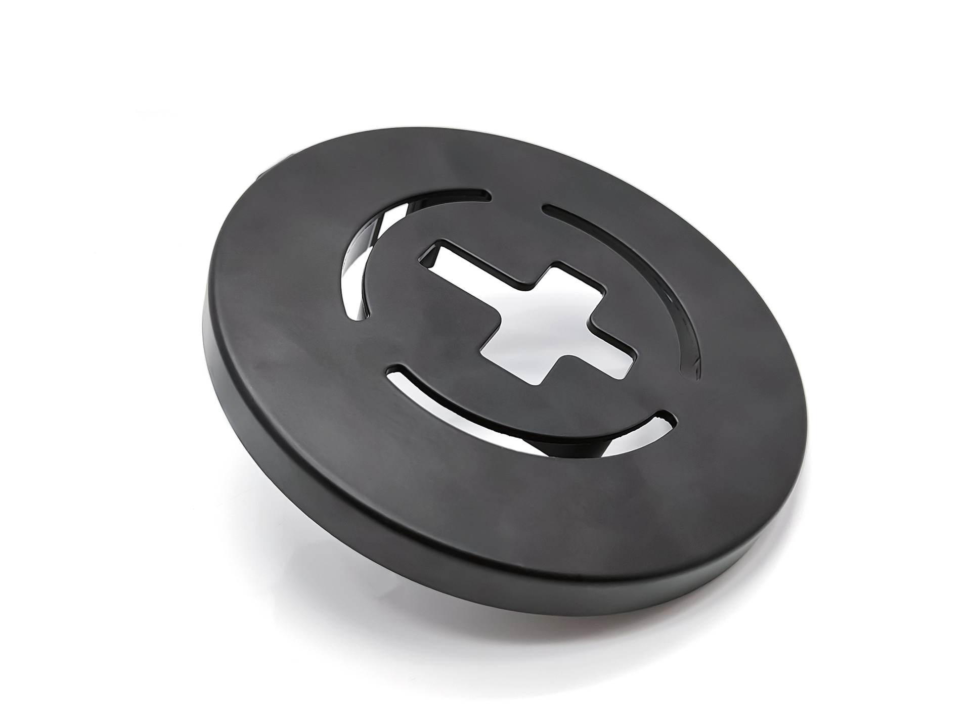
Use Gradual Transitions
Avoid sharp transitions between thick and thin regions. Sudden changes in wall thickness can cause turbulent metal flow and incomplete filling. Use fillets or tapering (draft) to create smooth transitions.
Use fillet radii ≥ 1.5 mm to reduce stress concentrations
Apply draft angles of 1°–3° to aid demolding and maintain dimensional stability
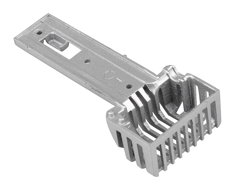
Control Thermal Gradients
Varying wall thicknesses cause inconsistent heat dissipation, leading to localized shrinkage and hot spots. Design engineers should identify and mitigate thermal mass concentration using simulation software during the design phase.
Design Issue | Cause | Preventive Solution |
|---|---|---|
Shrinkage porosity | Thick sections solidify slower | Use cooling channels, cores, or chills |
Cold shuts | Thin walls solidify before full flow | Maintain section thickness or preheat mold zones |
Warping | Uneven cooling due to thickness variation | Use uniform wall design and proper gating layout |
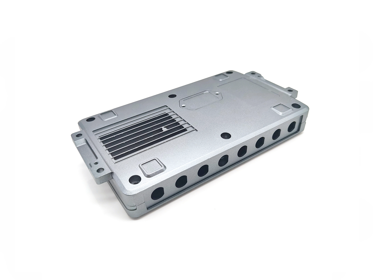
Incorporate Ribs Instead of Thick Walls
To increase strength without creating massive wall sections, use reinforcing ribs. Ribs reduce weight and improve stiffness while avoiding the heat retention issues of thick walls.
Recommended rib thickness: 60–75% of the adjacent wall
Rib height should not exceed three times the wall thickness
This approach is particularly practical in automotive structural parts and electronic housings, often made via aluminum die casting or zinc die casting.
Optimize Gating and Feeding Systems
Thicker areas require strategic placement of gates and risers to ensure full metal flow and compensate for shrinkage during solidification.
Gates should be directed toward thicker sections to fill heavier mass first.
Employ pressure-fed gating systems in high-pressure die casting (HPDC) to overcome premature solidification in thin walls.
Conduct Mold Flow Analysis
A crucial part of modern casting design is simulation. Neway uses flow simulation and thermal modeling to predict and eliminate casting defects before tooling begins.
This allows:
Identification of hot spots
Detection of air entrapment areas
Optimization of runner geometry and gate location
Such simulation tools are especially valuable in complex part geometries with ribs, bosses, and variable wall zones, where manual calculations fall short.
Align Tolerances with Wall Variation
Parts with varying wall thicknesses experience different cooling-induced shrinkage, which affects final dimensions. It’s important to specify appropriate tolerances as per ISO 8062-3 (casting tolerances) based on local wall thickness.
Thin-walled features: tighter tolerances (±0.10–0.20 mm)
Thick-walled sections: looser tolerances (±0.30–0.50 mm)
Collaborating early with your casting supplier ensures realistic and functional tolerances for every geometry.
Use Prototyping to Validate Geometry
Prototyping with urethane casting or 3D printing is recommended for parts with complex thickness profiles. These methods allow engineers to test assembly fit, cooling behavior, and weight distribution before full-scale die development.
Conclusion
Managing wall thickness variation is a critical component of successful metal casting design. By applying these best practices—from geometry optimization and gating control to simulation and prototyping—manufacturers can avoid costly defects, improve material efficiency, and enhance the mechanical integrity of the final part. At Neway, every casting design undergoes rigorous DFM review, thermal modeling, and material validation to meet functional and production goals.