Why Do Paint Runs and Thin Edges Occur on Complex Die Cast Housings?
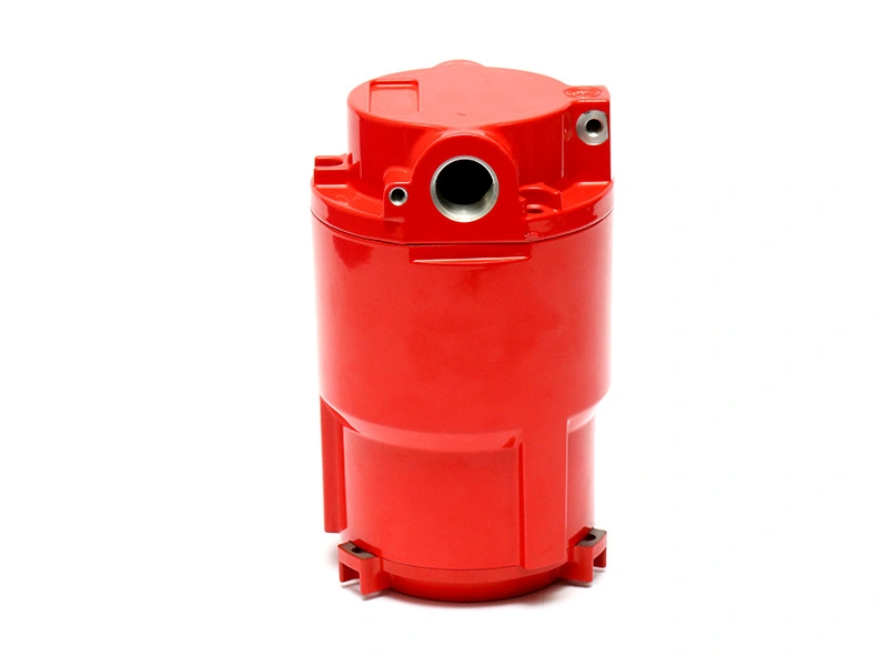
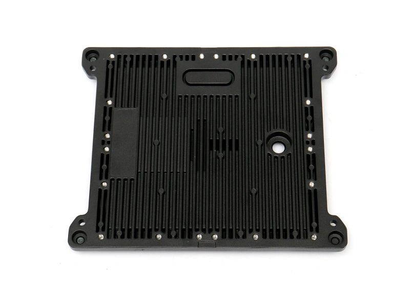
Paint runs occur when too much wet film remains mobile on a surface before flash, while thin edges occur when film pulls away from a sharp transition or receives insufficient spray. Complex die cast housings combine vertical walls, underside faces, recesses, fins, bosses, openings and mask boundaries, so one gun path can overbuild one zone and miss another.
How Part Orientation Changes Film Distribution
Gravity acts on wet coating before it sets. A surface that is horizontal during spray can become vertical before flash, allowing material to sag. Lower edges collect drainage; upward-facing pockets can pool; downward-facing recesses can receive low coverage. Qualification should use the actual rack, rotation and line sequence.
Map defects to orientation. Recurrent runs at the same lower flange suggest deposition or flash behavior, while random runs can indicate mix, equipment or operator variation. Do not polish the defect away before recording its location and direction.
Geometry | Likely Paint Risk | Review |
|---|---|---|
Vertical wall | Sag/run | Wet film, overlap and flash |
Sharp outer edge | Thin film | Edge preparation and coverage validation |
Deep recess | Dry spray or missed area | Gun angle, airflow and access |
Lower lip | Pooling/drip | Orientation and local deposition |
Mask transition | Ridge, bridge or tear | Spray overlap and removal timing |
How Application Variables Create Runs or Dry Spray
Gun distance, angle, travel speed, overlap, atomization, fluid delivery, coating condition and air movement affect deposition. Too much local wet film promotes runs; droplets that lose too much volatile material before reaching the part can create dry, rough overspray. Settings must remain within the coating and equipment qualification.
Painting process control should record material identity, mix, usable life, viscosity or approved check, equipment settings, rack and environmental conditions. Operators should not correct a recess by slowing the entire pass and overloading broad adjacent faces.
Why Sharp Edges Often Have Less Protection
Liquid film tends to draw away from a sharp edge, and a narrow edge offers little area for deposition. Burrs and ragged trim edges make the condition less predictable. Round or break edges only to the extent allowed by part function and drawing. Edge preparation should occur before cleaning and pretreatment.
Do not judge edge coverage only by color. A pigmented film can appear continuous while being below the qualified thickness. Use representative edge sections or other validated checks during development and include high-risk edges in environmental testing.
How Flash-Off and Coat Sequence Affect Sagging
Insufficient flash leaves the first layer mobile when the next coat arrives. Too much total wet film can trap solvent or water and increase sagging or popping. An excessive delay can exceed the recoat window. Follow the coating supplier's approved sequence, time, part temperature, airflow and humidity.
Sequence Error | Possible Defect | Evidence |
|---|---|---|
Short flash | Run, solvent pop or intermixing | Time/environment and defect map |
Excess wet film per pass | Sag or slow volatile release | Wet-film zone readings |
Long recoat delay | Intercoat adhesion weakness | Recoat-window record |
Uneven part temperature | Different flash/cure by section | Part-temperature profile |
How Substrate Defects Can Look Like Application Defects
Oil or silicone can create craters; porosity can contribute to pinholes during heating; machining coolant can bleed from threads; rough blast residue can appear as texture. A run is usually a film-flow issue, but not every uneven spot is caused by spray technique. Inspect substrate and preparation records before changing gun settings.
Mechanical treatment such as sand blasting cast aluminum can create a controlled profile when qualified, but dirty media or trapped abrasive adds defects. Blasting does not replace degreasing or chemical preparation.
How to Build a Coverage and Defect Map
Divide the housing into critical cosmetic faces, ordinary visible faces, hidden faces, functional edges, recesses and masks. Record wet and dry film, appearance and defect type by zone and orientation. Include top, bottom and interior transition views. The map should drive gun path and inspection sampling.
Approve boundary samples for texture, orange peel, edge coverage and minor defects where visual criteria are needed. Use defined lighting, viewing distance and angle. A photo alone can shift color and hide film flow, so retain physical masters under controlled storage where practical.
How to Investigate and Contain a Defect Lot
Hold the lot back to the last verified condition. Separate defects by rack position, time, coating mix, operator/robot program and casting source. Preserve representative parts before repair. Check wet-film records, flash, part cure profile and equipment condition.
Run a controlled trial that changes one credible cause. Increasing thinner, reducing cure or adding another coat without approval can create hidden weakness. Confirm correction on difficult zones and repeat adhesion or environmental checks affected by the change.
When Rework Is Acceptable
Use only an approved repair route defining cleaning, sanding or removal, recoat window, layer identity, total film, cure and appearance. Runs can sometimes be leveled and recoated, but the repair must not expose or damage the substrate treatment or create excessive film at fits.
Track rework count and location. Repeated repair at one edge is a process signal, not a normal production condition. A capable route controls deposition and flash so both broad surfaces and difficult edges remain inside the qualified system.