How Should Buyers Define Coated, Uncoated and Transition Zones on a Cast Part?
Buyers should define coated, uncoated and transition zones with a surface ownership map tied to the controlled drawing. Each zone needs a functional reason, an acceptance method and a realistic boundary. A note that says “mask all critical surfaces” is not enough because the coating supplier cannot infer which areas control sealing, grounding, location, press fit or appearance.
The map should identify at least three conditions. Coated zones require full specified coverage and the appropriate cosmetic or protective standard. Uncoated zones must remain free of coating and residue because they perform a function. Transition zones allow the physical mask edge to vary within a dimensioned band while still protecting the functional area.
Why Transition Zones Need Their Own Definition
Tape, caps and plugs do not create a zero-width theoretical boundary. Powder can feather toward an edge, build a small ridge, bridge a gap or chip when the mask is removed. If the drawing controls only the nominal line, otherwise acceptable parts may be rejected for harmless edge variation, or functionally important areas may be left insufficiently protected.
A transition band gives the supplier a manufacturable window. Its width and location should come from function. A gasket land may need a minimum clean width plus margin for mask placement. A grounding pad may need a guaranteed bare contact area while allowing a narrow coated border. A decorative line visible to the customer may need a much tighter visual master.
Surface Zone | Typical Requirement | Verification |
|---|---|---|
Exterior A-surface | Complete coverage, approved color and texture | Visual master and thickness map |
Hidden coated cavity | Protective coverage with lower cosmetic grade | Coverage inspection at accessible points |
Thread or precision bore | No coating that affects gauge or fit | Plug/thread gauge after mask removal |
Gasket or grounding area | Guaranteed clean functional width | Dimension, cleanliness and function check |
Transition band | Mask edge allowed within a controlled window | Visual or dimensional boundary check |
How to Build the Surface Map
Begin with assembly. Mark every interface that contacts another part, seals fluid, carries electrical current, establishes location or receives a fastener. Then identify visible surfaces and the expected observation condition. Remaining surfaces can be assigned an appropriate hidden or general finish class rather than receiving an unnecessarily expensive premium standard.
The map should be visible in the 3D model or drawing views and use unique labels. Color coding can help in a work instruction, but the controlled engineering definition should not depend on color alone. Dimensions or datum references are needed where the boundary affects function. The post-machining route should use the same zone definition so machined pads and bores are not inadvertently coated.
Include holes and edge depth. “Mask this face” may leave ambiguity about whether the adjacent chamfer, counterbore, thread lead-in or sidewall is protected. A sectional view can show how far the coating or mask extends into an opening. This is especially important when a plug seats inside a hole and creates a boundary below the surface.
How to Approve Mask Removal and Edge Condition
Inspection occurs after masks are removed. Check adhesive residue, trapped plugs, loose coating lips, tears, chips and powder bridges. A bare surface can still fail if it contains residue that affects sealing or conductivity. A coated surface can fail if the edge breaks away during the first assembly.
Functional gauges should follow the actual requirement. Threads need the specified gauge or fastener check. A grounding pad may require a resistance check under a defined contact method. A gasket land needs width, cleanliness and surface acceptance. These results provide stronger evidence than a photo of the masked part before coating.
The powder coating supplier should retain the approved mask drawing, plug or tape identification where relevant, rack orientation and first-article photographs. If a supplier changes masking material or placement method, the transition-zone and functional checks should be reviewed before the change reaches production.
Hypothetical Gasketed Enclosure Example
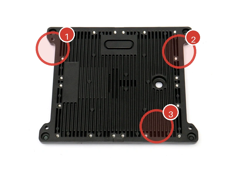
Consider a hypothetical enclosure with a powder-coated exterior, a protected internal cavity, a machined gasket land, six threaded holes and one grounding boss. The gasket land is defined as an uncoated zone with a minimum clean width. A transition band sits outside that width so the tape edge can vary without entering the seal path. Thread lead-ins and the first thread are protected by plugs, while the grounding boss has its own bare contact diameter.
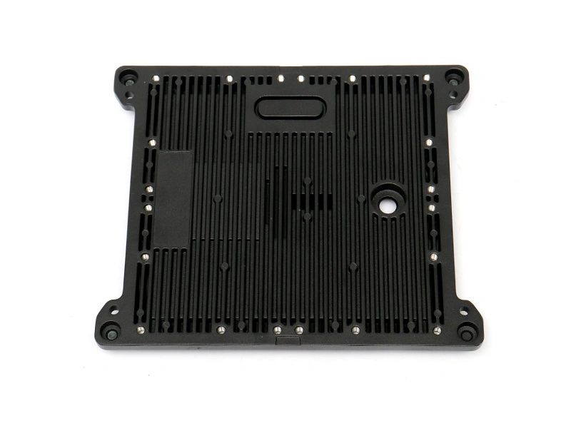
The first article is inspected after mask removal. The supplier checks the gasket width, thread gauges, grounding contact and coating edge. The buyer also reviews whether the transition is visible in final assembly. This example illustrates a release method; it is not a customer drawing or a report that the pictured housing uses these zones.
Drawing Input | Question to Resolve |
|---|---|
Zone label | Is the surface coated, bare or transitional? |
Boundary dimension | How much mask-edge variation is acceptable? |
Functional check | What gauge or test proves the interface works? |
Visual class | Under what lighting and distance is the edge judged? |
A strong surface map makes coating, machining, inspection and assembly agree before samples are produced. It also prevents the common cost mistake of treating every hidden surface as cosmetic while leaving truly functional transitions undefined.