Where Should Powder Coating Thickness Be Measured on Complex Castings?
Powder coating thickness should be measured at numbered, repeatable locations that represent large flats, critical exposure zones, recess entrances, interior surfaces and fit-sensitive boundaries, while remaining within the gauge manufacturer's geometry limits. A convenient exterior flat alone cannot represent a casting with ribs, pockets, edges and masked openings.
The map should separate required numeric locations from visual-only or functionally gauged zones. Tight radii, narrow ribs, sharp edges and deep cavities may not provide enough probe seating area for a valid eddy-current reading. Those areas need another approved form of evidence rather than a forced number from an unsuitable location.
How to Select Representative Measurement Zones
Start with the part's functional and exposure map. Include a cosmetic face if appearance and film build are linked, a protected exterior surface if corrosion exposure is important, and a location near a recess where deposition is expected to be difficult. Add measurements near fit boundaries only when the probe can sit correctly without crossing a mask edge.
Zone | Why Measure It | Common Limitation |
|---|---|---|
Broad exterior flat | Tracks process center and cosmetic build | May be easier to coat than the rest of the part |
Recess entrance | Detects local deposition difficulty | Probe may be influenced by nearby edge |
Interior wall | Confirms specified internal coverage | Limited probe access or curvature |
Near masked interface | Protects assembly transition | Reading can cross coating feather edge |
Edge or narrow rib | May be a service-critical area | Often invalid for direct probe measurement |
How Calibration, Substrate and Curvature Affect Readings
Aluminum castings are commonly checked with an eddy-current instrument suitable for nonferrous substrates. The operator should verify the probe on uncoated substrate or representative reference material and use certified shims or standards near the expected range. The active method may reference ISO 2360, ASTM D7091 or another buyer-approved procedure.
Cast surface roughness creates local variation between peaks and valleys. Curvature and thin edges change the electromagnetic response. The gauge instructions define minimum substrate thickness, edge distance and curvature conditions. Calibration on a smooth flat panel may not control a small curved casting feature. The powder coating inspection plan should state which reference condition is used.
How Many Readings Should One Reported Value Contain?
The quality agreement should define whether a reported result is one probe reading, an average of several readings within a small spot or a zone average. Repeated readings can reduce random variation, but averaging must not hide a local minimum in a critical location. Record individual values when the minimum and maximum matter.
Sampling also depends on production risk. First article mapping can use more locations and more parts to establish distribution. Routine production may use a smaller stable set combined with visual and functional checks. A rack-position study can show whether upper, lower, leading or shielded parts behave differently.
The map should define how to treat an unusually rough local casting surface. Multiple readings within a small marked spot may characterize scatter, but the averaging rule must be approved before results are known. Polishing a test spot solely to make the gauge stable changes the substrate and is not representative unless that preparation is part of production.
Instrument records should include gauge identification, probe, verification standards and operator or station. This allows a later shift in readings to be separated from a real coating change, a replacement probe or a calibration-condition difference.
How to Write a Repeatable Thickness Map
A robust map uses photographs or drawing views with point numbers, dimensional references and probe orientation. It identifies zones that cannot be measured, states the alternative acceptance method and records the instrument type. It also distinguishes the component map from a witness coupon used for cure, color or laboratory testing.
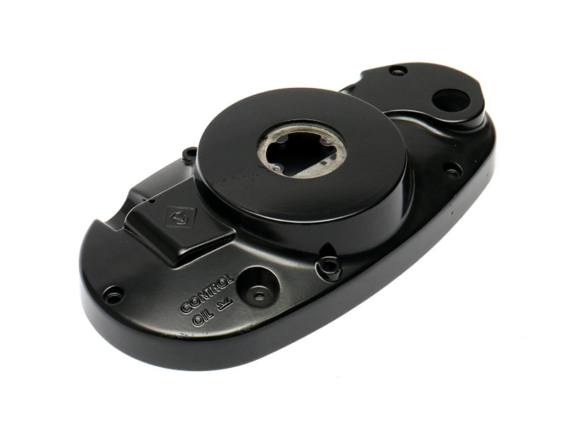
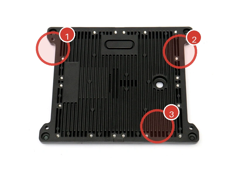
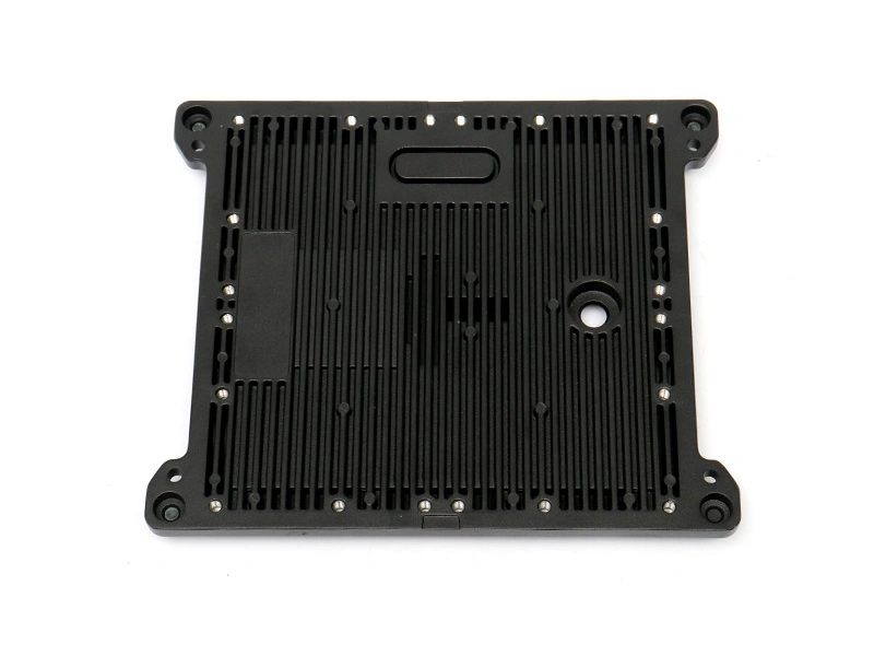
Consider a hypothetical ribbed cover. Point A is centered on the main exterior flat, Point B is midway down an accessible interior wall, Point C sits a defined distance from a recess opening, and Point D is near but not on a masked bore transition. The drawing marks narrow rib edges as visual-only. This produces repeatable evidence without claiming that one flat reading represents every surface.
When upstream geometry or machining changes, the measurement map may also need revision. A new rib, deeper pocket or wider machined pad changes deposition and probe access. Coordination with the complete post-process route keeps coating measurements aligned with the delivered part revision.
Map-Control Item | Required Detail |
|---|---|
Point identity | Number, view, distance from features and probe orientation |
Gauge basis | Instrument, probe, substrate verification and standards |
Reading rule | Individual, spot average or zone average |
Acceptance window | Minimum, maximum and any zone exceptions |
Sampling | First article, rack study and production frequency |
Unmeasurable zones | Visual, section, coupon or functional alternative |
Good thickness inspection is selective rather than random. The map should capture the geometry most likely to affect protection or function while respecting what the instrument can measure accurately. That makes data comparable across lots and prevents false confidence from easy but unrepresentative readings.