Why Is Powder Coating Often Thin in Recesses and Heavy Near Exposed Edges?
Powder coating can be thin in recesses and heavy around exposed openings because charged particles follow electrostatic field lines and the spray's air path. Field strength concentrates at accessible projecting geometry, while a cavity can shield its deeper surfaces. Repeated gun passes intended to reach the recess may add more powder to the surrounding rim before enough reaches the interior.
This pattern is influenced by geometry, grounding, voltage, powder flow, gun angle, distance, rack orientation and application sequence. It should not be assigned to a single cause from appearance alone. A thickness map and controlled trial are needed to determine which adjustment improves the actual part.
What the Faraday-Cage Effect Means on a Casting
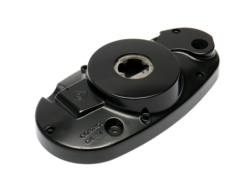
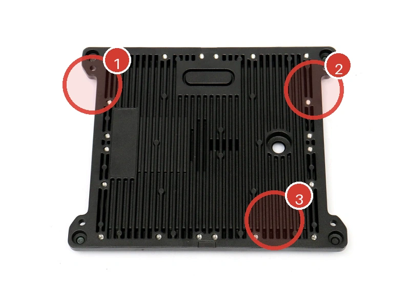
In powder application, a recessed corner or deep pocket can create an electrostatic condition in which charged particles deposit preferentially near the opening instead of continuing to the deepest surface. The effect becomes more difficult with narrow entrances, deep cavities, closely spaced ribs and sharp internal corners.
Increasing voltage without evidence may make the field concentration stronger or contribute to back-ionization on already heavy areas. The operator may need a different voltage strategy, lower powder flow, revised gun angle or a second controlled pass. The appropriate route depends on equipment and powder guidance; it is not a universal setting.
Influence | Possible Effect | Evidence to Review |
|---|---|---|
Deep narrow recess | Reduced particle access at depth | Depth-specific visual and DFT map |
Poor grounding | Unstable attraction or inconsistent build | Clean contact, resistance and rack condition |
High surrounding buildup | Rim receives repeated passes | Gun path and local maximum readings |
Sharp internal corner | Difficult coverage and flow behavior | Geometry review and qualified acceptance |
Dense rack loading | Neighboring parts shield spray access | Rack-position comparison |
Why an Exposed Edge Can Still Have Weak Protection
A heavy reading near an edge does not prove that the smallest edge radius has adequate protective coverage. During flow and cure, liquid coating can pull away from a sharp line, leaving a reduced film at the exact edge while nearby flats remain thick. Probe geometry may also prevent a valid measurement directly on the edge.
Edge condition should be controlled through casting and trimming quality, radius where design allows, coating-system selection and an appropriate inspection method. General guidance on how anti-corrosion coatings protect die castings helps explain why substrate, pretreatment and film continuity work together.
Which Process Adjustments Should Be Trialed?
A useful trial changes one controlled group of variables at a time. Possible adjustments include rack orientation, ground-contact cleaning, gun angle, distance, voltage stage, powder flow, application order and part spacing. The trial should record local measurements at the recess entrance, accessible depth and surrounding rim, not only an overall average.
Geometry may be the dominant constraint. A larger radius, wider access, reduced cavity depth or revised rib spacing can make coating more repeatable. When the part cannot change, the buyer may accept a zone-specific limit, use another protective route inside the cavity or mask a functional interior surface. The powder coating service evaluation should state the chosen boundary.
Powder reclaim condition, particle-size distribution and humidity can also influence transfer and flow, but they should be investigated with process records rather than guessed from one part. A controlled trial records the powder lot and booth condition so an apparent geometry improvement is not confused with a material or environmental change.
Racking must maintain a dependable conductive path throughout the run. Hooks that gradually accumulate cured powder can raise resistance and create position-dependent deposition. Cleaning frequency and contact-point acceptance therefore belong in the production control plan.
How to Release a Recess and Edge Acceptance Plan
Classify surfaces by function and exposure. A deep hidden cavity may need continuous visual coverage rather than a numeric reading if the probe cannot reach it. A recess carrying fluid, salt or condensate may need stronger evidence or a different coating design. Exposed cosmetic rims need both appearance and maximum-build control to avoid texture or fit problems.
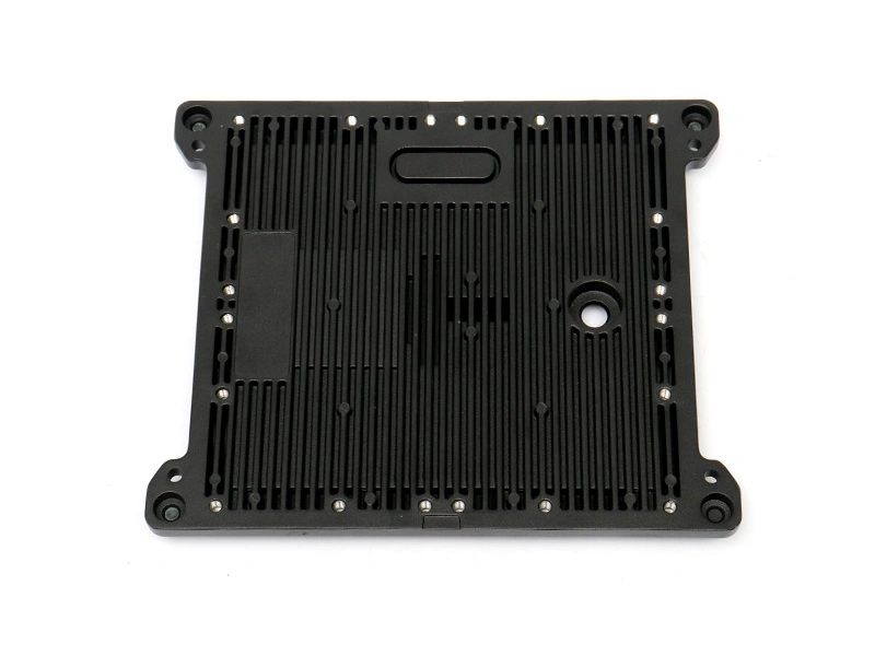
For a hypothetical finned housing, the map records exterior flats, accessible fin valleys, a recess entrance and the raised rim. A rack study compares upper and lower positions. The team does not infer a thickness at inaccessible depth; it uses agreed visual coverage or a representative section trial. This scenario is an inspection design, not a Neway result.
Acceptance Zone | Primary Risk | Release Evidence |
|---|---|---|
Recess entrance | High rim, low transition | Numbered DFT points |
Accessible recess wall | Low local build | Qualified probe readings |
Inaccessible depth | Unknown coverage | Visual rule, section trial or alternate protection |
Exposed rim | Excess build and texture | Maximum DFT plus finish master |
Sharp edge | Film pullback | Design radius and edge-specific inspection |
Thin recesses and heavy rims are geometry-sensitive deposition problems. The correct response is to map the pattern, verify grounding and access, trial controlled adjustments and set zone-specific evidence. Applying more powder everywhere can increase outer buildup without solving the protected area.