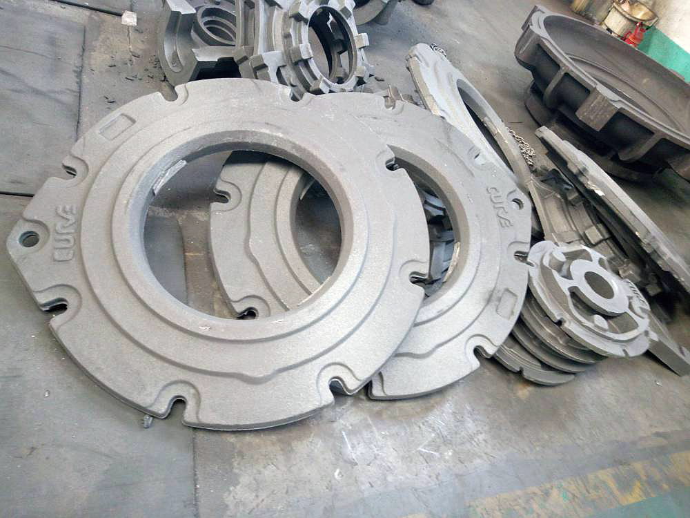
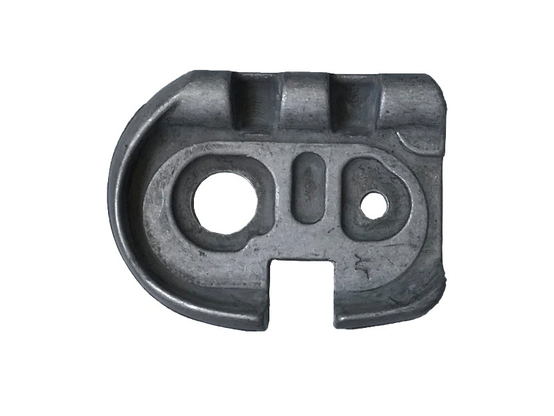
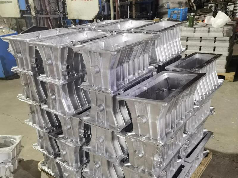
Sand casting handles complex external geometry by dividing a consumable mold around a pattern or by printing mold segments directly; it handles internal geometry with removable bonded-sand cores. Because the mold and cores are broken after the metal solidifies, the casting does not need to release from a permanent rigid die. Undercuts, hollow bodies and curved passages therefore become possible, provided the design can still be molded, assembled, filled, fed, vented, cleaned and inspected.
The mold cavity creates most outside surfaces. A conventional pattern leaves an impression in two or more sand sections. Draft and a practical withdrawal direction protect that impression when the pattern is removed. Stepped parting, loose pieces or additional mold segments can form local re-entrant contours, but each interface adds placement and mismatch risk.
A sand core creates a void because metal flows around it. Core prints locate the core in the mold; supports and vents address forces and gas. After shakeout, the core is broken and evacuated through openings. An external pocket may be made by either a mold projection or a core depending on parting, strength and assembly. The supplier should identify the chosen formation route on a sectioned mold concept.
Binder-jet printing can produce mold and core geometry directly from data, avoiding pattern and core-box withdrawal constraints. This helps with curved branches, compound splits and low quantities. It does not remove build-volume, resolution, sand strength, binder gas, depowdering, handling or metal-compatibility limits. Printed mold segments still need closures, vents, gates, risers and a safe assembly sequence.
Compare a printed-sand route with a rapidly made pattern using actual capacity and mold count. For repeat orders, a reusable pattern or core box may be more economical. For one intricate trial, printed sand may avoid several pieces of tooling. The baseline sand casting process still controls melting, pouring, solidification and cleaning in either route.
| Feature | Formation issue | Foundry risk | Buyer check |
|---|---|---|---|
| Thin remote rib | Long narrow flow path | Misrun or cold junction | Section and gating review |
| Heavy boss at a wall | Late-solidifying mass | Shrinkage or distortion | Feeding concept and first-pour inspection |
| Branching passage | Core assembly and gas path | Shift, breakage or retained sand | Core prints, vents and cleaning access |
| Across-parting detail | Mold-half relationship | Mismatch or flash | Defined datum and inspection state |
Geometric detail competes with foundry physics. Thin regions can freeze before filling, while nearby heavy regions need continued liquid-metal feeding. Narrow mold projections may erode. Isolated pockets may trap gas. Radii and gradual transitions support mold strength and solidification, but their appropriate size depends on alloy, scale and molding route.
A passage is not manufacturable merely because a core model fits inside it. Spent sand needs an exit, and cleaning tools or media need access. Long blind branches can retain sand. Small openings can prevent inspection or make a plug strategy necessary. Define cleanliness according to function, especially for fluid, lubrication or thermal circuits.
Gate and riser contacts also require removal and dressing access. Mark surfaces where grinding is permitted and protect walls or cosmetic contours that must not be thinned. If a feature cannot be cleaned without damage, opening the passage, casting separate pieces or machining and closing an access may be a better design.
Sand casting can place near-net material around a complicated envelope, but sealing faces, bearing bores, threads and assembly datums often need machining. Each feature should be labeled as cast, machined or created in a later assembly. Allowance must cover mold and core variation while preserving minimum wall after cleanup.
Dimensions contained in one mold half behave differently from dimensions crossing parting or relating separate cores. Do not apply one tolerance to the entire complex part. Establish rough datum targets for the first machining setup and inspect the casting condition before machining hides stock or core-location problems. Post-machining should be quoted by feature, setup and acceptance requirement.
External dimensions and accessible passages can be measured directly or scanned with a defined alignment. Hidden networks may need borescope inspection, flow testing, leak or proof testing, radiography, computed tomography or destructive sectioning. Each method has material, thickness, resolution and access limits. Select the method from the failure mode rather than requesting every test.
A cooling jacket may need continuity, cleanliness and leak acceptance. A structural hollow section may need core-location and internal-quality evidence. A nonfunctional weight-reduction cavity may only need minimum wall protection. State the test condition and what conclusion it supports.
Send controlled CAD and drawing, exact alloy, section map, critical passages, datums, machined zones, minimum walls, surface requirements, cleanliness and functional tests. Ask the foundry to return parting, mold segments, core assembly, prints, vents, gates, risers, cleaning openings, allowances and inspection points. An early engineering review should also identify geometry that needs splitting or another process.
Sand casting handles complexity well when the feature map proves more than shape. The external cavity and internal cores must survive assembly and pouring, then leave a casting that can be cleaned, finished and accepted. That complete chain defines feasible geometry.