
Die-Cast Enclosure: 200 Pieces, Six Flatness Failures
In an example record, six of 200 aluminium die casting enclosures measured 0.15 mm across the opening face against a 0.10 mm callout. A new ejector layout and a stress relief ahead of the opening-face cut followed, and a recheck reported 0.06 mm on the face, measured free of the fixture.
The part comes from an enclosure programme: an aluminium box at 120×90×45 mm, 2.5±0.2 mm walls, 2.0 mm ribs, 380±30 g, all design targets. The alloy is ADC12 to ASTM B85 in the as-cast F temper, a grade pending foundry confirmation. The route runs die casting, two milled faces, tapping, coating and inspection.
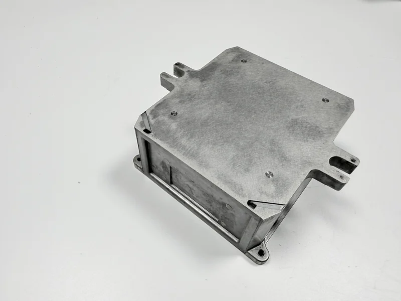
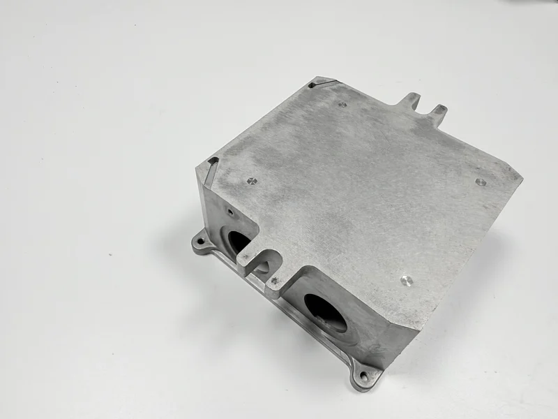
What did the 200-piece run fail on?
Six parts out of 200 measured 0.15 mm on the opening face, above the 0.10 mm callout. The record names those six; it does not say whether they went to rework or scrap, or whether the line stopped.
A size check would not catch it, because flatness is not a size. The record carries no floor reading, so a floor that followed the pins stays a gap, and a face that fails at the bench is found after the milling is booked.
| Record says (pieces, mm) | Record is silent on |
|---|---|
| Lot of 200 pieces | Whether the six went to rework or scrap |
| Six parts at 0.15 mm, callout 0.10 mm | How many parts were rechecked |
| Recheck 0.06 mm, part free of the fixture | What gauge produced it |
Where did the 0.15 mm come from?
Two loads act before the finishing cut: the pins that strip the 2.5 mm floor and the clamp that holds the frame for the top-face cut. The record's first fix is the ejector layout, which points at the pins; it does not separate the two, so which one dominated belongs to the flatness diagnosis.
Cost treatment here is general practice, not this record: an ejector change is tool work quoted once, with a first article behind it, and a clamp change is bench work quoted on the parts. The record does not say who carried either cost.
How was the opening face measured?
Acceptance is a surface plate and a 0.10 mm feeler blade: the face rests on the plate, and the blade must not enter anywhere around the frame. The part has to sit free of the fixture; a clamped face reads to the clamp.
The blade is a go or no-go check and cannot produce a 0.06 mm figure. The record reports 0.06 mm without naming the gauge, inspector or bench, and no CMM report appears in it. What produced that figure stays a gap.
As general practice, the check costs bench minutes per part and needs no fixture.
Which two changes brought it to 0.06?
The first change was a new ejector layout in the die. The record gives no pin count.
A stress relief was the second change. The example record places it before the opening-face cut; whether the route includes one, and where it sits, is pending foundry confirmation. Temperature and hold are absent too.
The record lists only these two changes, and both were fixed before the recheck lot; one is die tool work, the other a process step. General practice puts the layout in tool work and the relief in a furnace slot and a second setup, one paid once and one paid on every part.
What did the recheck prove?
The recheck gave 0.06 mm on a part measured free of the fixture, inside the 0.10 mm callout, with no count given. The figure is consistent with the two changes rather than proof of them, and it cannot separate the ejector contribution from the relief contribution. No dates appear either, so the interval between the two runs stays open.
| Check item | Target (mm) | Record |
|---|---|---|
| Opening face flatness: 0.10 blade must not enter, part free | 0.10 | 0.15 first lot; 0.06 recheck, gauge not named |
| Floor thickness | 2.5 ± 0.2 | No reading; a floor that follows the pins carries the face |
What would this case change in a new drawing?
The record behind this case is tabled above. What a new drawing can add is the method: name the datum and the free state, name the gauge that reads the face, and write the batch size that triggers a recheck. It is silent on the number rechecked, what happened to the six, what gauge produced 0.06 mm, and the relief parameters.
This chain is consistent with two changes, not a controlled comparison. This case does not prove the yield of a whole production batch, because one 200-piece lot, one die and one recheck are the whole record. A drawing that names the gauge and the free state is what a quote needs to price the check.
Two boundaries sit outside this record: a wall thinner than 2.5 mm, and a face read after powder coating. A shell cover case runs casting and CNC on one order; the wall thickness comparison covers the thin wall.
Send the drawing with the opening face as the datum, the gauge and blade size named, the free state stated and the batch size, so a quote can price die work and bench check apart.