Machining Sealing Faces on Cast Housings: Flatness, Surface Texture and Leak-Control Planning
Machining sealing faces on cast housings begins with the seal system, not a generic milling specification. A compressible gasket, O-ring, formed-in-place seal and metal-to-metal interface respond differently to flatness, waviness, texture, lay, porosity, groove geometry and assembly load. The drawing should translate those functional needs into measurable surface and dimensional controls.
Ra alone cannot release a sealing face. The same average roughness can contain a directional cutter track that crosses a gasket land, local waviness between bolts or an isolated pore connecting a pressure path. A flat free-state face can distort when bolts tighten, while a face measured only in the machining fixture can spring back after unclamping. Dimensional inspection and a specified leak or pressure test answer different questions and should be correlated.
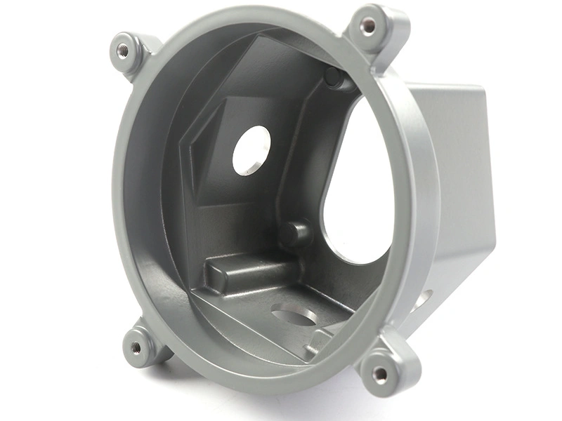
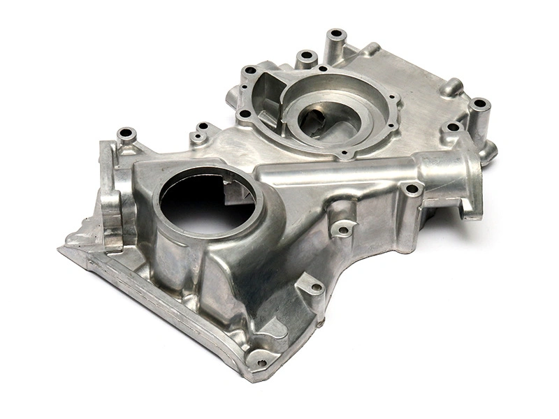
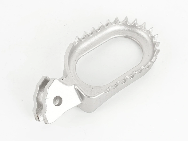
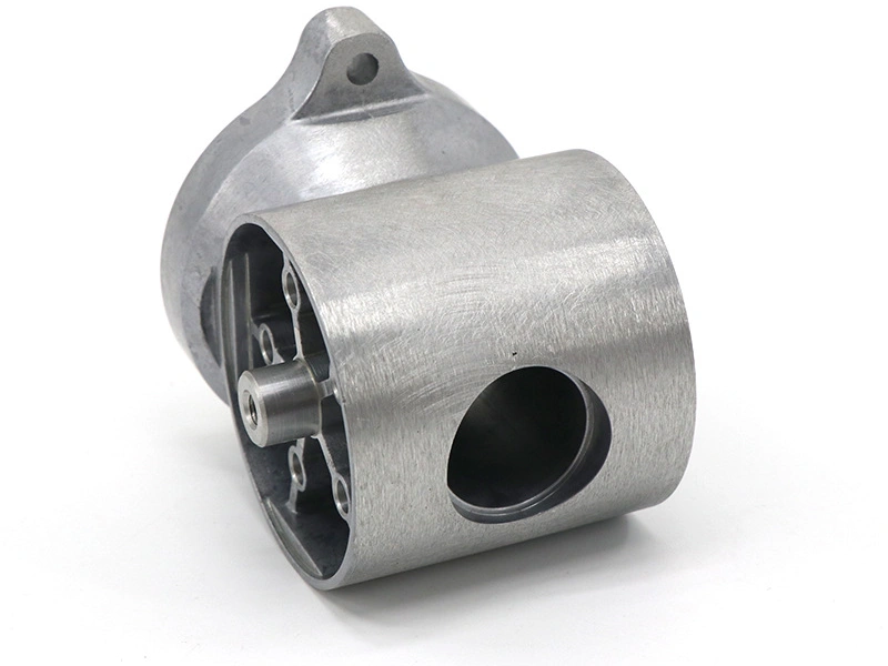
The images show housing geometry with flange-type openings and machined interfaces. They do not establish the final application, seal type or any achieved value.

How Seal Type and Failure Mode Define the Machined Interface
A flat gasket needs enough continuous land and compression to conform without extrusion, crushing or a channel across the pressure boundary. An O-ring needs groove width, depth, volume, edge condition and surface compatible with squeeze and motion. A liquid sealant needs dispensing, cure and gap capability. A metal-to-metal seal depends heavily on form, texture and assembly stiffness.
Seal Direction | Machining Focus | Failure to Prevent |
|---|---|---|
Compressible flat gasket | Land width, flatness, lay and bolt-load distribution | Low compression or cross-land channel |
Static O-ring | Groove depth/width, edge radius and surface continuity | Insufficient squeeze, twist, cut or extrusion |
Formed-in-place seal | Dispense path, gap and cure-compatible cleanliness | Voids, contamination or incomplete bond |
Metal-to-metal interface | Form, waviness and fine surface control | Local gaps under assembly load |
Dynamic seal interface | Finish direction, wear and geometry | Seal lip damage or fluid pumping |
Product engineering and the seal supplier should define the functional limits from pressure, medium, temperature, material and assembly. The machining supplier then proposes a capable route. Copying a roughness or flatness number from another housing can produce an expensive surface that still leaks.
How Functional Datums Control Sealing-Face Machining
The machining setup should locate the casting from references that preserve the seal's relationship to ports, bores, fasteners and mating components. Locating from a variable cosmetic wall can machine a flat face in the wrong functional position. First-operation cast targets may create a machined primary plane and bore; later operations can use those datums to finish the seal interface.
Clamp force must react through stiff supported geometry. Pulling a flange against a fixture can create an apparently flat cut that warps in free state. Measure clamp displacement during qualification and inspect released parts. If the drawing controls the assembled state, define the restraint, bolt pattern, torque or load and mating reference used for that measurement.
Datum Decision | Why It Matters | Evidence |
|---|---|---|
Primary fixture plane | Sets sealing-face orientation | Stable targets and free-state result |
Bore or port axis | Controls flow/assembly alignment | Position/profile to face |
Bolt pattern | Determines assembly load distribution | True position and mating fit |
O-ring groove reference | Controls squeeze and concentricity | Depth, width and profile from functional frame |
Inspection alignment | Prevents best-fit hiding functional error | Drawing datum-based report |
The resource on CNC post-machining for assembly fit provides useful context. The project drawing and datum scheme remain the acceptance authority.
How Flatness, Parallelism, Waviness, Roughness and Lay Differ
Flatness controls the complete surface relative to two parallel planes without a datum. Parallelism controls orientation relative to a datum. Waviness describes longer-wavelength shape variation between form and roughness. Ra averages short-wavelength profile; Rz responds differently to peaks and valleys. Lay describes surface direction. A face can pass Ra and fail flatness, or pass flatness while a cross-seal tool witness creates a leak channel.
Measurement setup must define filtering, cutoff, evaluation length, direction and location for profile parameters. Flatness evaluation needs an appropriate point or scan pattern that covers high and low regions, not three points chosen near bolts. CMM, surface plate indicators and optical methods each have capability and fixturing limits.
Characteristic | Question Answered | Cannot Prove Alone |
|---|---|---|
Flatness | How much does the entire face depart from a plane? | Texture or seal compression |
Parallelism | How is the face oriented to a datum? | Local finish or free-state stability |
Waviness | Are there longer-spaced highs and lows? | Microtexture or leakage directly |
Ra/Rz | What short-scale profile exists under the method? | Whole-face form and directional channel |
Lay/tool witness | Does texture create a directional path? | Seal load or internal porosity |
Retain raw traces or maps during first article. A single rounded report value loses the location and direction needed to investigate a later leak.
How O-Ring Grooves, Gasket Lands and Bolt Patterns Form One Stack
O-ring squeeze depends on groove depth relative to the mating face, ring cross-section, tolerances, thermal condition and material. Groove width and volume must accommodate deformation. Edge radius or chamfer should avoid cutting the ring while retaining the designed geometry. Concentricity or profile to the port can matter where pressure acts unevenly.
For flat gaskets, land width and bolt spacing control compression. Bolt-hole position, thread quality, boss stiffness and mating-part flatness influence load. A nominally flat housing can bow between bolts, and a thin flange can dish around tightened fasteners. Analyze the complete assembly instead of assigning all responsibility to the machined surface.
Stack Element | Machining/Inspection Input | Functional Link |
|---|---|---|
Groove depth | Datum-based depth/profile | Seal squeeze |
Groove width/volume | Width, corners and finish | Expansion and extrusion control |
Gasket land width | Continuous usable contact | Compression path |
Bolt pattern | Position and thread relationship | Load distribution |
Mating face | Counterpart form and material | Combined gap under load |
How Porosity, Tool Marks and Burrs Create Leak Paths
A surface opening can be harmless outside the seal track or critical when connected across it. Tool marks can act as capillary paths when they run from pressure to atmosphere. A step at cutter overlap, chatter band or scratch can cross the land. Burrs can hold mating surfaces apart or cut an O-ring. Cleaning debris can prevent local compression.
Map every indication relative to seal boundaries. Use “void indication observed after machining” until morphology and distribution support a mechanism. If internal extent matters, qualified X-ray, CT or destructive sectioning may contribute; X-ray inspection has projection and resolution limits and does not replace leak testing.
Toolpath should minimize witness steps and uncontrolled cross-land grooves. A single continuous face path can reduce joins but may create spiral lay; alternative paths change force, flatness and cycle time. Qualify the route with the actual seal system rather than declaring one universal best pattern.
How to Clean, Protect, Mask and Package Finished Sealing Surfaces
After machining, remove chips, burrs, coolant and cleaning residue from the face, groove, bolt holes and ports. Do not use abrasive pads or uncontrolled scraping that changes texture. Clean dry air must not add oil or drive chips deeper into passages. Define inspection after final cleaning because debris can hide pores or scratch the surface during assembly.
If painting or powder coating follows, mask the entire functional surface and define the transition. Coating on the land can change flatness, groove volume and bolt seating; mask adhesive can leave residue. The post-process route should validate mask removal, edge condition and final cleanliness.
Protection Stage | Control | Risk if Weak |
|---|---|---|
Deburring | Named tool, direction and removal limit | Rounded land or hidden defect |
Cleaning | Residue-free face, groove and passage | Assembly gap or contamination |
Masking | Coverage and clean transition | Coating on seal or adhesive residue |
Handling | Gloves and nonfunctional contact points | Fingerprints, dents and scratches |
Packaging | Rigid nonabrasive separation | Face-to-face rub or particle imprint |
How Dimensional Inspection and Leak Testing Should Be Correlated
Dimensional inspection verifies the defined geometry; leak testing verifies the tested component or assembly under named conditions. A dimensional pass with a leak failure can indicate surface-connected porosity, contamination, seal damage, mating-part error or test-fixture leakage. A dimensional failure with a leak pass still violates the drawing unless engineering approves a deviation.
Define test medium, pressure or vacuum, stabilization, duration, temperature, allowable rate, calibration, sealing fixture and whether test seals cover the product seal track. Pressure-decay results depend on volume and temperature. Bubble methods locate some paths but may have sensitivity and interpretation limits. Test evidence should stay linked to the same serialized or lot-controlled part and dimensional report.
CMM inspection planning can preserve datum-based geometry, but it must be correlated with surface and leak evidence on the same interface.
Result Pair | Investigation Direction | Release |
|---|---|---|
Dimensions pass / leak passes | Normal process trend | Release if all other requirements pass |
Dimensions pass / leak fails | Porosity path, cleanliness, seal or test fixture | Hold and preserve evidence |
Dimensions fail / leak passes | Drawing nonconformance remains | Engineering disposition required |
Dimensions fail / leak fails | Form/load plus integrity investigation | Contain affected population |
Hypothetical Validation Matrix for a Bolted Flange
Consider a hypothetical cast housing with a machined gasket land and eight-bolt pattern. First article records free-state flatness, waviness, Ra/Rz at radial and circumferential directions, tool-witness map, land width and bolt-hole position. The face is then assembled to a controlled mating plate using the defined gasket and tightening sequence.
Measurement under assembly load identifies local bow between bolts. A pressure-decay test and approved leak-location method are run at specified conditions. Matched samples at surface and flatness boundaries show whether the acceptance window protects function. Packaging trials confirm the land remains undamaged before assembly.
This is a planning example, not a reported customer result and not evidence that the pictured part is a pressure housing.
What to Include in a Sealing-Face Machining RFQ
Provide casting and finished models, 2D datum and tolerance definitions, seal type and supplier requirements, medium, pressure/vacuum and temperature, mating-part data, bolt/load method, machining stock, allowed indications, cleaning, coating/masking, quantity, inspection state and functional test. Identify whether free-state, restrained-state or both forms are controlled.
For CNC machining, request the setup/datum concept, clamp-distortion study, toolpath direction, inspection map, cleanliness route and leak-test proposal. Do not accept a quote that lists Ra and flatness without confirming the seal system and test boundary.
RFQ Item | Buyer Defines | Supplier Returns |
|---|---|---|
Seal system | Type, material, squeeze/load and service | Machining and inspection route |
Datum/form | Free/restrained state and relationships | Fixture and clamp-control plan |
Texture/lay | Parameters, method and prohibited marks | Toolpath and measurement evidence |
Porosity | Zone and indication rules | Map, containment and NDT proposal |
Cleanliness/protection | Residue and packaging requirement | Cleaning, masking and handling method |
Leak test | Conditions, limit and sampling | Fixture, calibration and raw record |
A sealing face is successful when its form, texture, location, cleanliness and assembly load create a continuous functional barrier. Machining and leak testing should be planned together because neither a smooth number nor a passing gauge alone proves the complete seal.
How Material, Temperature and Coating Change the Sealing Interface
Aluminum housings, steel fasteners, polymer seals and a different mating material expand and relax at different rates. A joint validated at room temperature can change groove squeeze, bolt preload and flange form at service temperature. Heat from machining and washing also affects inspection; a warm aluminum flange should not be compared directly with a drawing condition intended at a controlled temperature.
Surface treatment changes the stack. Conversion coating may add a thin interface, while powder or wet paint can add significant and locally variable build. Unless the seal system was designed and qualified over that finish, functional lands, O-ring grooves, bolt seats and grounding areas often require controlled masking. Mask edges, adhesive and coating creep then become inspection features.
Environment or Material Input | Possible Interface Change | Validation Direction |
|---|---|---|
Housing temperature | Aluminum expansion changes gap and groove size | Inspect/test at defined thermal condition |
Fastener material | Different expansion and preload retention | Assembly load through service cycle |
Gasket compression set | Contact pressure declines with time/heat | Aged or cycled leak validation |
Coating thickness | Changes land, bolt seat or groove volume | Masking or coated-stack qualification |
Service fluid | Seal swelling, extraction or corrosion | Material compatibility and functional test |
Seal drawings should state whether dimensions apply before or after finish and at which temperature. When a finish change is proposed, recheck not only corrosion performance but also edge buildup, seal contact, fastener seating and cleaning compatibility.
How to Establish Process Capability and Reaction Limits
Capability work should include casting cavities, normal stock variation, fixture positions, tool-life stages and warm production conditions. Record flatness/profile maps and roughness at fixed seal-specific locations rather than reducing every face to one average. Include the mating-part or leak-test population when functional correlation is part of the release.
Separate common process variation from special events such as chipped inserts, fixture chips, clamp-pressure change, casting tool repair or cleaning failure. A control chart on one roughness location cannot detect flange bow or a single cross-land scratch; combine trend points with complete-zone visual inspection and periodic dense mapping.
Production Signal | Immediate Reaction | Containment Boundary |
|---|---|---|
Flatness trend moves | Check clamp, locator, stock and thermal state | Since last accepted form check |
Roughness/lay shifts | Inspect cutter, runout and tool life | Parts from suspect tool interval |
Cross-land scratch | Stop handling/deburr route and preserve face | Since last complete visual release |
Leak failure with dimensions passing | Protect assembly and locate path | Test fixture, seal lot and casting population |
Masking/coating contamination | Hold finishing route and inspect residues | Since last clean unmask verification |
After any rework, repeat all characteristics the action could change. Re-facing affects position, flatness, texture, stock and wall; local deburring affects edge and land width; cleaning affects visible pores and residue. Record the original nonconformance and final state under one part identity.
What a Seal-Supplier Review Should Return
The seal supplier or product engineer should return the required squeeze or compression window, groove/land geometry, surface-direction limits, permissible gaps, material and fluid compatibility, temperature range, assembly lubricant if any, mating-surface expectations and validation method. Machining engineering should return how those inputs become datums, tolerances, toolpaths, cleaning and inspection.
Where the seal recommendation uses a range, test production extremes and tolerance stack rather than one nominal assembly. Document which requirement controls when seal guidance and existing drawing notes conflict. This prevents a machining supplier from choosing a convenient generic finish while the assembly team assumes a different interface.
Mating-component revisions must remain linked to seal validation. A new plate material, stiffness, surface finish, port edge or bolt-seat geometry can change contact even when the cast housing drawing is unchanged. Repeat the relevant dimensional, load and integrity evidence before treating the new counterpart as interchangeable.
Correlate dimensional boundary samples with assembly evidence before reducing production inspection. Select housings near the approved flatness, texture and position limits, assemble them with identified mating parts and seals, and record bolt sequence, torque or tension, temperature and leak response. A nominal part alone cannot show whether the specification protects the worst acceptable stack. If a boundary sample fails, the team should revise the interface requirement or process, not average it with easier assemblies.
The correlation record should preserve the actual face map and leak-test trace under one part identity. That lets engineering distinguish a broad flange tilt from a local scratch, pore or seal-installation error. Routine gauges can then monitor proven predictors, while periodic dense mapping and functional audits check that the original relationship still holds after cutter, fixture, seal or mating-part changes.
FAQ
Why Is Ra Alone Insufficient for Approving a Machined Sealing Face?
How Should Cutter Lay Be Oriented Relative to a Gasket or O-Ring Path?
How Can Bolt-Pattern Distortion Change Sealing-Face Flatness in Assembly?
What Cleanliness Controls Protect a Finished Sealing Surface Before Assembly?
How Should Dimensional and Leak-Test Results Be Correlated for Cast Housings?