Aluminum Gravity Casting for a Flanged Elbow: Ten Steps
Aluminum gravity casting carries this 150±20 g flanged elbow on three sequences. The gate sits on the outer bend, so the inner bend is not the inlet, with the riser at the flange feeding it. The Sa 2.5 blast comes before the flange is turned, and the 0.9 MPa test runs after the flange holes are drilled.
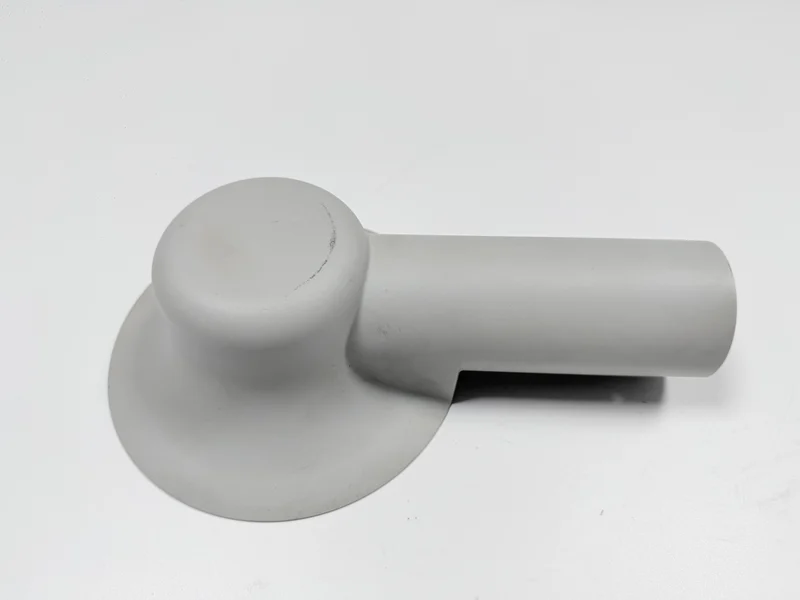
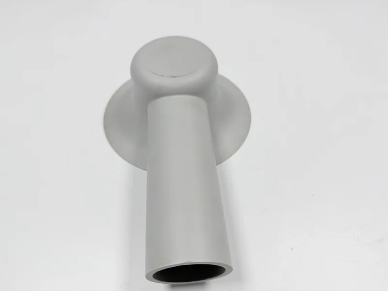
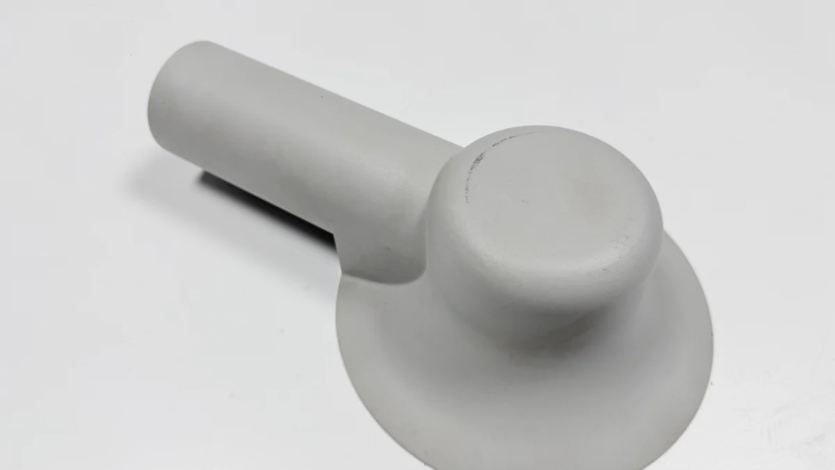
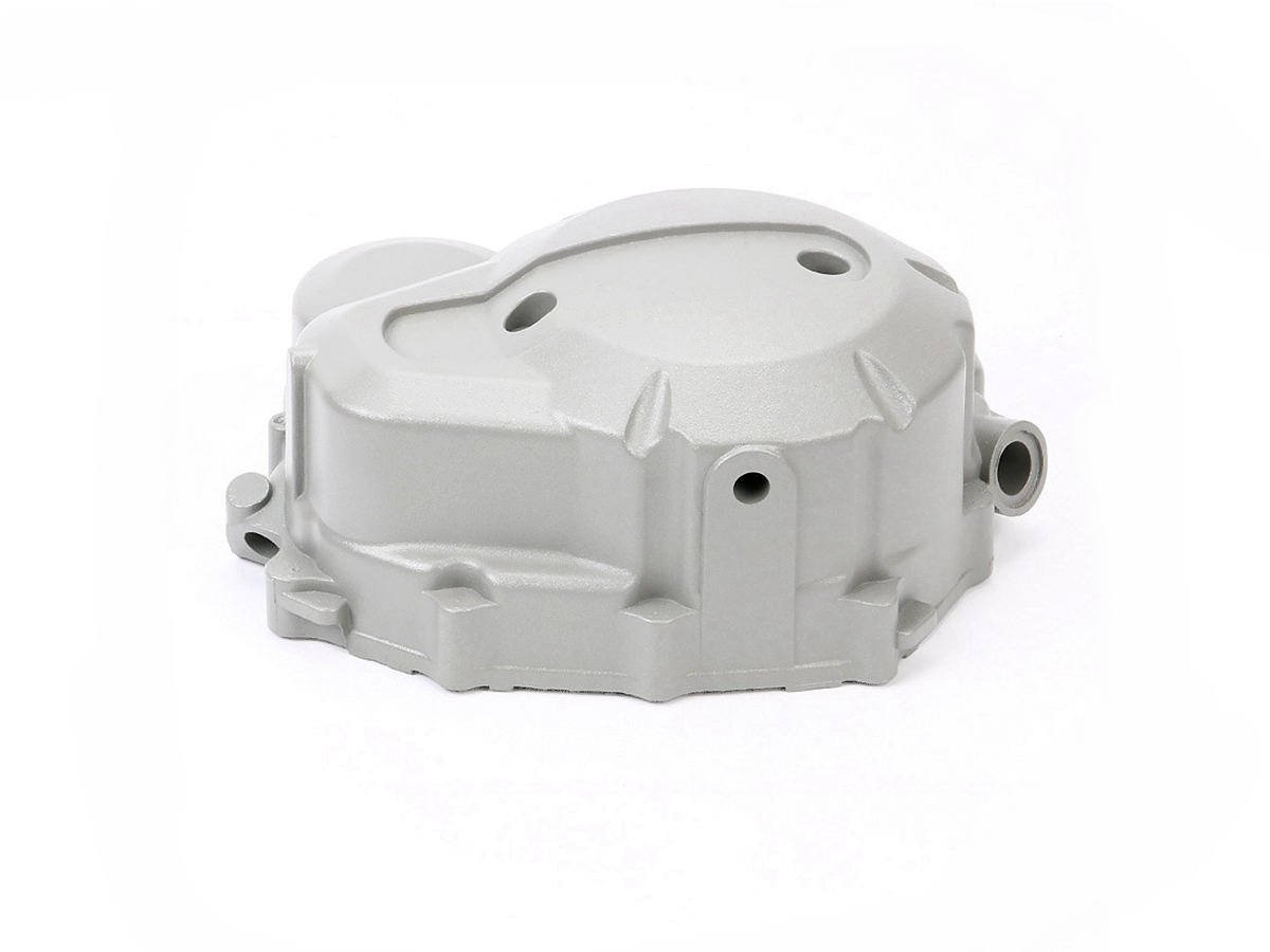
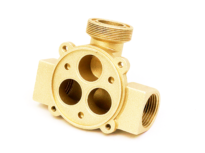
The part is a 75×60×55 mm elbow in A356 (GB/T 1173 ZL101A, pending foundry confirmation), cast in the as-cast F temper with no T6. It runs on a steel metal-mold gravity casting line, one or two parts to a mold, with a preheated cavity and a machined flange face and port.
The route runs in ten steps, from melt and degas to final inspection, and each step hands a tolerance to the next. The table lists each step's setting, limit and check.
| Step | What it sets | Limit or check | Where it is checked |
|---|---|---|---|
| 1 Melt and degas | Gas in the melt | Degassed and refined, typical | Furnace record |
| 2 Pour | Fill of the 4–6 mm wall | 700–740 °C metal, 250–350 °C mold | Cold shut at the port end |
| 3 Open the mold | Release without distortion | Part temperature within the process sheet band; no drag mark at the port wall | Press record and visual on the casting |
| 4 Cut gate and riser | Feed path removed | Cut back to cast surface | Gate pad |
| 5 Deburr | Edges under the gasket | No burr at rim or lip | Visual and touch |
| 6 Blast | Surface before machining | Sa 2.5, ISO 8501-1 | Visual comparator |
| 7 Turn face and port | 0.05 mm flatness, Ø20 H9 bore | One setup, one datum, no re-chuck | Plate and feeler gauge, plug gauge |
| 8 Drill flange holes | Bolt pattern on face datum | Position per drawing | CMM |
| 9 Pressure test | Wall soundness at the bend | 0.9 MPa held 60 s, no leak | Bench record |
| 10 Final inspection | Every callout on one record | Drawing limits | CMM, PT, visual |
Why use gravity casting instead of sand casting for an elbow?
A sand mold and a steel mold both deliver an elbow, and both need the flange face flat to 0.05 mm and the Ø20 H9 port cut afterwards. The sand casting arrives with more stock and takes more setups to reach them. The choice sits in what the casting hands to the cut: a steel mold pulls heat out fast, so a 4–6 mm wall sets with a tighter skin and a flange that needs less stock.
A welded stainless elbow is the third route, for corrosive duty at a higher part cost and with a weld seam to inspect.
Which tolerances do I have to fix before you cut the mold?
Five dimensions and one weight are fixed before the mold is cut; four are drawing targets, pending the drawing. Those four are 0.05 mm flatness on the flange face, Ø60±0.5 mm on the cast flange, Ø20 H9 in the port and 0.1 mm perpendicularity of the port axis. The wall sits at 4–6 mm and the finished weight at 150±20 g. The machined callouts therefore decide how much stock the casting carries.
How much stock do the face and the bore carry at blast-state delivery, and on what datum is the casting handed over? Are the 0.05 and the H9 judged free-state after the cut, or predicted before it?
| Feature | Target (mm) | Allowed range | Verified with |
|---|---|---|---|
| Flange face flatness | 0.05 (drawing target) | 0.05 mm blade does not enter, part free | Plate and feeler gauge |
| Flange outside diameter | Ø60 as cast (drawing target) | ±0.5 | CMM |
| Port bore | Ø20 H9 (drawing target) | Go enters, no-go does not | Plug gauge |
| Port perpendicularity to flange face | 0.1 (drawing target) | ≤ 0.1 | CMM |
| Wall thickness | 4–6 | Per drawing section | Section gauge on the drawing section |
How do you keep the inner bend from shrinking as it cools?
The inner bend of this 150 g elbow is the last section to freeze: it joins the flange disc and the tube, so its section carries more mass than either one alone. A hot spot is a zone that solidifies after its neighbors, so it needs liquid feed after the thin tube wall has set.
Metal enters through the gate, the inlet on the outer bend; the riser is the feeder, a reservoir at the flange end that keeps feeding as the part shrinks. The outer-bend gate keeps the hot spot off the inlet, and the riser feeds toward the inner bend. Both positions are the tooling target, pending foundry confirmation.
A gate on the inner bend would put the hot spot at the inlet, where the thin tube cuts it off from the riser. A pore that forms there sits under a closed skin, so only the pressure test finds it.
What is the thinnest wall aluminum gravity casting can fill?
The thinnest wall on this elbow is 4 mm, which is not thin for gravity casting in a steel mold, because the metal enters a preheated cavity. A 250–350 °C preheat lowers the chill from the steel, but it does not make the cavity hot.
The mold is cooler than the metal, so it skins the front of the stream, and two streams that meet without fusing leave a cold shut, a line where the metal never welded. Cold shut is a visual criterion, read at the port end where the wall is thinnest, and mold temperature drift costs cycle time there.
What pouring and mold temperatures does A356 need?
A356 (AlSi7Mg), reported as GB/T 1173 ZL101A pending confirmation, is one of the aluminum casting alloys used here and pours at 700–740 °C into a mold at 250–350 °C. Both are typical windows rather than numbers from this plant. Below the band the metal reaches the port end half set; above it the casting keeps more shrinkage and sticks to the mold.
The melt is degassed and refined before the pour, because hydrogen dissolved in aluminum comes out as gas pores while the metal sets. Those pores sit under a sound skin and show only when a cut opens them.
Because degassing runs on every melt, skipping it is not a saving; it moves the cost to the machined face, where a pore that opens on the flange face rejects the part after turning.
Why is the elbow blasted before the flange face is turned?
The blast runs at step six, before the face and the port bore are turned, so the abrasive meets the as-cast skin and never a machined surface. Sa 2.5 to ISO 8501-1 is the cleanliness grade this elbow ships with, and neither machined surface is blasted after machining.
Abrasive on the flange face rounds the edge the gasket seats on, and grit in an H9 bore scores the bore wall. That is why the sand blasting step runs ahead of the turning, and why a reversed order is paid twice.
How are the flange face and the port turned in one setup?
One setup cuts the flange face and the Ø20 H9 bore in one clamping. The two ends face different directions, so the setup takes two passes without releasing the part. The face just cut becomes the reference for the port's 0.1 mm perpendicularity and the sealing face for the gasket.
Three jaws on a Ø60 mm flange bend it elastically; a free part sits on a surface plate, where a feeler gauge with a 0.05 mm blade is the check. Because re-chucking adds one more spring-back, a second cut costs another setup and another test.
When are the flange holes drilled?
The flange holes are drilled at step eight, after the face and port are turned and before the pressure test. Hole positions follow the flange-face datum, so a hole cut before the face is machined would ride a surface that still moves. Count and bolt size come from the mating part shown on the drawing, and the drawing sets the pattern. Because those holes index that part, a shifted pattern rejects a part whose face is good.
What leak test does each elbow get before it ships?
Every elbow is pressure-tested: the flange and the port are clamped, the part is filled, and 0.9 MPa is held for 60 s. A part with no leak through the wall is released, and that figure is the acceptance criterion for the test, not a pressure rating for the casting. Because the bench runs after the turning and the drilling, a leak there writes off the machined part.
A connected pore path through the inner bend lets the medium through, and the leak shows where the hot spot sat; the skin stays closed over it. The same bench logic on a cast housing is set out in a pump housing study.
How do you check the flange face and the bore before shipping?
Five checks cover the finished elbow before shipping. The face is checked on a surface plate with a 0.05 mm feeler gauge, the port on a Ø20 H9 plug gauge, and the port axis on a CMM (coordinate measuring machine).
Penetrant testing, or PT, finds defects that break a machined surface, and a magnifier reads the as-cast skin. Neither replaces the bench, because the pore path under the skin stays closed.
A caliper reads two points across the port, so it can pass an oval bore that the H9 plug gauge rejects. That miss costs a machined part, because the failure surfaces only after turning and drilling. The plug gauge checks the full form, and the plug gauge decides acceptance.
When does sand casting beat gravity casting for an elbow?
Sand casting wins when the elbow has loose tolerances and no pressure test, because a pattern costs less than a steel mold. Add a 0.05 mm flatness callout, an H9 port and a pressure test, and the metal mold pays back through less stock and fewer setups.
Where a program mixes cast parts with assembly, the release logic is set out in a cast hardware case.
| Condition | Sand casting | Metal mold gravity |
|---|---|---|
| Tooling | Pattern, lower first cost | Steel mold, fixed cost across the lot |
| Cast surface | Rougher, deeper cut | Tighter skin, less stock |
| 0.05 mm flatness and H9 port | More cut, more setups | One setup after the blast |
| Pressure test | Same bench; frequency per drawing | Test on every part |
| Where it fits | Small lots, no tight callout | Repeat lots with a test |
What does a flanged elbow quote contain?
The quote on this elbow has five blocks: the mold, the melt and pour with the gate and riser cut, the blast, the turning of the face and port with the drilling, and the test with final inspection.
Because the gate and the riser sit in the mold, the first block is tooling, and a drawing change after the mold is cut lands there. Because the face and the port are cut in one setup, the turning block carries one clamping and one gauge set.
Mold cost per part falls as the lot grows, since one or two parts per shot means a small lot carries more mold per part. The bench is a per-part station, so the test block follows the lot rather than the mold.
A quote that arrives as one number hides which block moves when the drawing changes. Send the 2D drawing with the 0.05 mm flatness callout, the Ø20 H9 port, the 0.1 mm perpendicularity callout and the test pressure, plus the lot size.
FAQ