Aluminum Casting Port Ovality: Demolding or the Chuck?
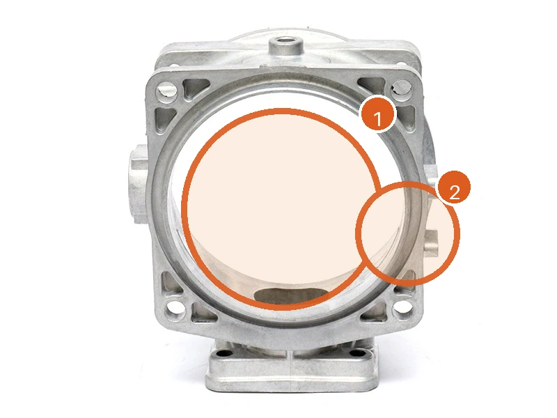
The Ø20 H9 port can leave the machine oval, at the ejection stroke or in the jaws that hold it for turning the port and the flange face. H9 is the bore's tolerance class, a narrow band on the drawing; the plug gauge, a go/no-go gauge, decides whether the finished bore passes.
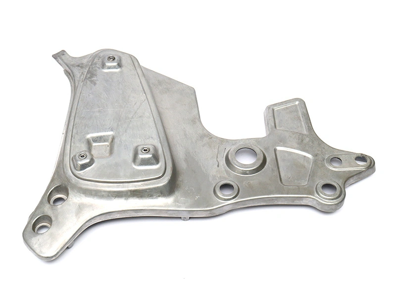
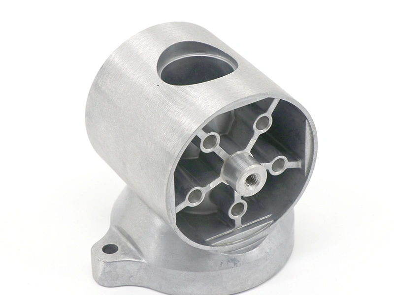
The part is a 75×60×55 mm flanged elbow in A356 (GB/T 1173 ZL101A, pending confirmation) at 150±20 g, cast by metal-mold gravity casting in the as-cast F temper. Its Ø20 H9 bore and the 0.1 mm port-axis perpendicularity are drawing targets to confirm; the 4–6 mm wall is the nominal section.
Why is my aluminum casting port out of round after machining?
Ejection pushes the hot casting off the core, and three jaws on the chuck, the lathe work holder, grip that thin wall before the cut. Both happen before gauging: the first leaves the cast bore out of round, and the jaws press it round only while closed.
The cut is round while the jaws hold it, and the free bore reads oval after they open.
Is the oval port the casting's fault or the machining's?
Two readings separate the sources, and only the finished one uses the H9 plug gauge. The as-cast bore carries machining allowance, so the go end cannot enter it. An inside micrometer, a three-point bore gauge or a CMM reads its largest and smallest diameter along two perpendicular axes; the difference is the cast ovality.
That difference must sit inside a drawing limit or one agreed with the foundry. A reading over the limit points at the ejection setup. A reading inside the limit, with the plug gauge failing after turning, leaves two suspects. An oval repeating the cast direction is the cast shape; one pressed only where a jaw sat is the fixture. The order decides the tooling: the ejection setup and the fixture are two separate jobs.
On the cast bore, a deeper radial cut cannot remove the oval: the thin wall springs back to the shape the ejection left. That route belongs to the ejection setup.
Can calipers check a 20 mm port for ovality?
No. A caliper across the wide direction passes, because it reads only the diameter through the two high points, not the narrow one. The Ø20 H9 plug gauge has two ends and judges the finished bore only: the go end enters the full bore and the no-go end stops at the chamfer. An oval bore lets the no-go end start in the wide direction; an undersized bore stops the go end at the mouth. The part sits free, because a clamped bore reads round. A gauge that stops short of full depth can pass an oval deeper in.
| Feature | Target (mm) | Allowed range | Measured with |
|---|---|---|---|
| Port bore | Ø20 H9 (drawing target) | Go end through, no-go end out | Ø20 H9 plug gauge |
| Port axis | 0.1 to the flange face (drawing target) | 0.1 or less, part free | CMM |
| Port wall | 4–6 (nominal section) | 4–6 | Caliper, wall section per drawing |
Why does the port have to line up with the flange?
The 0.1 mm perpendicularity keeps the bore square to the flange face, the datum for the joint. A tilted axis makes the flange bolts pull the joint sideways. A CMM, a coordinate measuring machine, reports the axis against that face; the reading must meet the 0.1 mm callout.
Turning the face and the port in one setup holds that axis, while a second setup re-datums the part and spends the tolerance.
Can an out-of-round port be fixed, or is it scrap?
An oval finished bore has two diameters. A re-cut must clean up the high point, which needs room below the H9 upper limit for one more pass; a low point under the lower limit cannot be built up. When the high point is at the top of the band, any cut that rounds the bore goes over the upper limit, and the part is scrap. A cut inside the band fixes the size, not the free-state oval, so the re-cut port faces the free-state check again.
Rework adds one more setup and a gauge check. That setup re-datums the part, so the CMM re-checks the 0.1 mm axis; the cut also takes more metal from the wall, so the 0.9 MPa, 60 s acceptance test runs again. When part after part fails the gauge, the readings decide the tooling: a cast failure points at the ejection setup, and a failure only after turning points at the fixture.
Send the drawing with the Ø20 H9 callout, the 0.1 mm perpendicularity and the gauge specified for the bore. Those three on one sheet bring the turning and inspection plans together.