Machining Porosity in Die Cast Aluminum: Risk Mapping, Acceptance and Process Feedback
Machining porosity in die cast aluminum usually means that cutting removed material above an existing subsurface void or discontinuity and made an opening visible. Machining can also tear an unsupported edge, drag material or leave tool damage that resembles a pore. Appearance alone cannot establish whether an indication came from trapped gas, shrinkage, an oxide-related discontinuity, inclusions or machining damage.
The correct response depends on location, size and distribution, connection to a pressure or sealing path, remaining wall, assembly load and the drawing's defect rules. One round opening on a hidden dry surface can have a different consequence from a smaller connected indication crossing a gasket track. Buyers need a map and functional decision, not a blanket “no porosity” statement without a method.
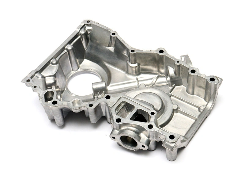
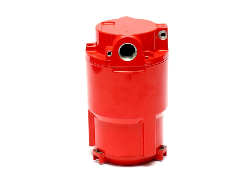
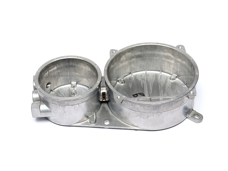
The images show cast housings with machined-type interfaces, bores and section changes. They support risk-mapping discussion only; no visible feature in the images is identified as porosity.

Why Machining Exposes Existing Voids Instead of Creating Internal Porosity
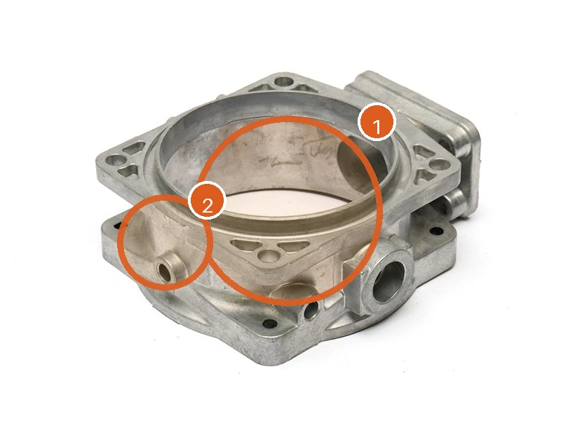
Internal casting porosity forms during filling and solidification; a cutting tool does not create trapped-gas or shrinkage voids inside sound metal. It can intersect a void distribution that was previously below cast skin. Deeper facing, boring or drilling exposes a new plane and therefore a different cross-section through the casting.
Machining can create separate surface damage. A worn tool, built-up edge, unstable fixture or interrupted cut can pull material from a thin ligament, smear an opening or chip an edge. Cleaning can dislodge trapped debris and make the indication appear larger. Preserve the as-found surface and tool/process records before polishing or re-cutting.
Observation | Possible Path | Evidence Needed |
|---|---|---|
Rounded isolated opening | Gas-pore-like indication | Section/distribution and casting records |
Irregular interdendritic-looking void | Shrinkage-like indication | Metallography and section context |
Thin folded or planar feature | Oxide-film or flow-related indication | Cross-section and qualified analysis |
Torn edge following tool direction | Machining damage or weak ligament | Tool, path and pre/post surface evidence |
Cluster after deep material removal | Intersected subsurface distribution | Depth map and upstream casting review |
Use “void indication observed after machining” until the mechanism is supported. This language keeps inspection and disposition accurate and prevents one visual clue from becoming an unsupported casting-process conclusion.
How Location and Function Change Porosity Criticality
A pore's consequence is controlled by what crosses or loads that surface. Cosmetic zones focus on visible appearance and coating. Threads need sufficient continuous flank material and pull-out capacity. Bearing seats need geometry, support and surface continuity. Seal lands need an uninterrupted contact path. Pressure boundaries need proven leak integrity and adequate remaining wall.
Machined Zone | Primary Risk | Decision Evidence |
|---|---|---|
Hidden nonloaded face | Loose material or downstream contamination | Zone-specific visual and cleanliness rule |
Cosmetic face | Visible pit after coating or finishing | Approved appearance boundary |
Thread flank | Reduced engagement or local breakout | Location, engagement and functional/load validation |
Bearing seat | Interrupted support, fit or wear | Size/form plus zone-specific discontinuity rule |
Gasket seal land | Leak path across contact track | Defect map, seal geometry and leak/function test |
Pressure wall | Connected path or insufficient section | Qualified leak/pressure and structural evidence |
Do not accept or reject by diameter alone. A small indication can be critical if it connects across a narrow seal track; a larger blind cavity outside the functional path may be acceptable under a defined standard. Clusters, planar indications and remaining ligament can matter more than one opening's apparent size.
Why Pore Morphology Is a Clue, Not a Root Cause
Round smooth openings are commonly associated with gas, while irregular interconnected voids can suggest feeding or shrinkage behavior. Folded, linear or oxide-associated features can relate to filling. These visual tendencies help select samples and inspection, but a machined two-dimensional surface shows only one cut through a three-dimensional condition.
Tool smearing, deburring, cleaning and lighting alter edges. A round section through an irregular void can look circular; a cluster can merge after further cut. Root-cause work should combine location by cavity and casting geometry, shot/process records, radiographic or CT evidence where capable, and microsections when destructive analysis is justified.
Information on metallographic analysis explains what sections can reveal. The cut plane samples one location, so it should be selected from a mapped indication and compared with controls.
How Machining Stock and Cut Depth Affect Exposure Risk
Machining allowance must be large enough to clean cast variation and establish final geometry, but unnecessary depth can intersect more subsurface volume, thin walls and move the final surface closer to internal discontinuities. Too little stock creates incomplete cleanup, cast-skin islands and unstable datum features. The correct allowance balances casting capability, draft, distortion, cutter access and final function.
Build a stock map from representative cavities and lots. Identify the minimum and maximum removed depth at sealing lands, bores, threads and thin sections. If one cavity consistently needs deeper cleanup, review casting position and tooling rather than applying a global deeper cut that raises risk everywhere.
Stock Condition | Machining Result | Risk |
|---|---|---|
Insufficient allowance | Uncleaned cast skin or low feature | Function and inspection inconsistency |
Balanced allowance | Complete cleanup with required section | Controlled through capability evidence |
Excess allowance | Deeper cut into casting | Void exposure and remaining-wall loss |
Uneven allowance | One side cleans deeply, another barely | Datum/warpage and casting-position issue |
Late design depth change | New final plane without casting review | Existing process may not support new zone |
The CNC machining and casting teams should approve allowance together. A machining drawing change that shifts a seal face or bore depth can require new porosity and leak qualification even when the casting die is unchanged.
Which Inspection Method Answers Which Porosity Question?
Visual inspection maps openings on the accessible surface but does not show internal extent. Radiography projects thickness into a two-dimensional image and can miss features aligned unfavorably or below resolution/contrast. Industrial CT can provide three-dimensional information, but voxel size, material thickness, reconstruction, artifacts and thresholding limit detection and measured volume. Neither method automatically predicts leakage.
Dye penetrant can reveal surface-connected discontinuities on suitable clean nonporous test conditions, but rough or naturally porous cast surfaces can create background and false indications. It does not map sealed internal voids. A microsection reveals morphology at one destructive plane. Leak and pressure tests answer functional integrity under defined conditions but may not locate the path or identify mechanism.
Method | Strongest Question | Key Limitation |
|---|---|---|
Visual/magnified map | Where are surface openings? | No internal connection information |
X-ray radiography | Are detectable density changes present through projection? | Superposition, orientation and resolution |
Industrial CT | What detectable 3D distribution exists? | Voxel/artifact/threshold and part-size limits |
Dye penetrant | Is a suitable discontinuity surface connected? | Background and no subsurface-only detection |
Microsection | What is morphology at this plane? | Destructive and highly local |
Leak/pressure test | Does the component meet defined functional integrity? | Does not identify root cause alone |
Resources on X-ray inspection and industrial CT imaging provide method context. The project plan still must define detectability, calibration references, region of interest, sampling and disposition.
How to Choose Use, Rework, Impregnation Evaluation or Rejection
Use-as-is requires evidence that the indication remains inside the drawing and functional acceptance. Local re-machining is valid only when stock, geometry and final tolerance permit it; cutting deeper can reveal more voids. Blending a sealing land can change flatness and roughness. Welding or filling is not automatically suitable for die-cast aluminum and can alter heat, distortion, coating and leak behavior.
Vacuum impregnation can be evaluated for suitable connected microporosity when the product, fluid, temperature, cleaning and downstream finish allow it. It does not restore structural metal, correct large shrinkage voids or repair a damaged thread. The process requires qualification of sealant compatibility, cure, post-cleanliness, leak performance and traceability. Do not claim it as a universal repair.
Disposition | Gate | Evidence After Action |
|---|---|---|
Use as-is | Zone and function remain acceptable | Recorded engineering disposition |
Local re-machine | Stock and tolerance permit | Final geometry and renewed indication check |
Impregnation evaluation | Connected leak path and compatible function | Qualified cleanliness, cure and leak result |
Other approved repair | Drawing and engineering authority permit | Full functional and finish revalidation |
Reject/scrap | Integrity cannot be demonstrated | Lot containment and root-cause feedback |
Rework instructions should limit depth, area and repeat count. Repeated attempts to “machine until clean” remove evidence and can create an under-thickness part that looks better but performs worse.
How One Finding Should Feed Back to the Casting Process
Contain the relevant part, machining fixture position, casting cavity, lot or shot range according to traceability. Inspect matched unmachined controls and other machined parts at the same zone. One indication can be random; a repeated geometric pattern or cavity association is stronger evidence of a systematic mechanism.
Review fill and solidification context, gate and overflow location, vent or vacuum records where applicable, local section thickness, cooling, shot/process window and tool condition. Do not change several casting parameters from one visual assumption. Establish a hypothesis, select evidence and confirm improvement across representative production.
The aluminum die casting process owns upstream correction. Machining supplies exact depth, coordinate, tool path and cavity/lot pattern needed to make that correction focused.
Hypothetical Investigation of Point Indications on a Seal Land
Consider a hypothetical housing where three point indications appear after finish facing of a gasket land. The team does not immediately call them gas porosity or reject the complete lot. It records coordinates relative to datums, opening dimensions, surface finish and whether each point crosses the specified seal track. Parts are linked to casting cavity, lot, machining fixture and cut depth.
Matched parts receive the specified leak test. Selected failed and passed parts are sectioned through mapped locations, and available radiographic or CT methods are reviewed for detectability before being used to screen more material. Investigation finds whether the indications are isolated, connected to a pressure path or associated with one geometry/cavity.
This is a decision example, not a Neway case or claim that the pictured parts contain pores. Final acceptance depends on the product's approved seal and integrity requirements.
What to Include in an RFQ and Porosity Quality Agreement
Provide the casting alloy and route, 3D and 2D definitions, machining stock and final cut depth, surface-zone map, pressure/sealing function, thread or bearing requirements, permitted repair, cleanliness, inspection method, sampling, traceability and lot-reaction rules. Define terms such as pore size, cluster, connected indication and measurement magnification when they control acceptance.
For integrated metal casting and machining, ask who owns the defect map, who can disposition parts and how machining evidence reaches casting engineering. The supplier should return a process route and inspection proposal rather than a universal zero-porosity promise.
Agreement Item | Buyer Decision | Supplier Evidence |
|---|---|---|
Functional zones | Seal, pressure, bearing, thread, cosmetic and hidden | Inspection and reaction by zone |
Machining depth | Nominal and allowable stock condition | Stock map and operation control |
Indication standard | Method, size, cluster and location rules | Calibrated visual/NDT records |
Functional test | Medium, pressure, time and limit | Traceable raw test result |
Repair boundary | Allowed, prohibited or approval required | Qualified process and reinspection |
Lot containment | Population and escalation rule | Cavity/lot/fixture traceability |
Machining-exposed porosity is manageable when the team preserves evidence, evaluates the exact functional path and feeds mapped information back to casting. The useful question is not whether every visible pore looks the same, but whether the delivered component meets its defined integrity and interface requirements.
How Cleaning, Deburring and Additional Cuts Can Change the Indication
Machining coolant, chips and smeared aluminum can partly fill an opening when it first leaves the tool. Washing, ultrasonic cleaning, compressed air or handling can remove that material and make the same void appear larger. Deburring can round an opening; aggressive abrasive cleaning can enlarge it. A second facing pass can intersect a wider section of the same void or expose a different member of a cluster.
Inspection timing must therefore be defined. A preliminary in-machine camera result is useful for process reaction, while final acceptance should occur after the specified cleaning and deburring condition. If penetrant, leak testing or coating follows, the sequence needs its own cleanliness and drying control. Do not compare an oily as-machined sample with a fully cleaned production part and call the difference process drift.
Post-Machining Step | Possible Change | Control |
|---|---|---|
Coolant wash | Removes smeared metal and trapped chips | Inspect before and after during qualification |
Compressed air | Clears or drives debris into openings | Clean dry air, pressure and direction |
Manual deburr | Rounds or blends indication edge | Defined tool, area and maximum removal |
Additional cut | Changes section through the void | Engineering stock and depth approval |
Surface finishing | Hides, opens or contaminates the feature | Final-state acceptance remains traceable |
When root cause is under investigation, retain one specimen without local rework and document every cleaning or cut. Destructive analysis loses value if the surface has been repeatedly blended and the original boundary cannot be reconstructed.
How to Write Zone-Specific Acceptance Without a Universal Pore Limit
Start by dividing the machined component into functional zones and naming the inspection state. Define whether opening size is measured by maximum dimension, equivalent diameter or another method, at what magnification and after which cleaning. State how spacing, clusters, edge distance and planar indications are handled. A “maximum pore size” note without these details invites different results from the same part.
For sealing and pressure zones, combine surface rules with a defined functional test. For thread and bearing zones, include continuous material and fit or load requirements. For cosmetic zones, retain an appearance master. Hidden nonloaded zones can have a different visual limit while still prohibiting loose material and contamination. Engineering should control deviations; operators should not make root-cause or safety decisions from photographs.
Acceptance Element | Required Definition | Ambiguity Prevented |
|---|---|---|
Inspection state | After named machining, cleaning and deburring | Different opening appearance by process stage |
Measurement | Scale, magnification, edge rule and dimension | Operator-dependent pore size |
Cluster | Spacing or combined-area logic | Many small openings accepted individually |
Functional zone | Drawing map and boundary | Hidden-face rule applied to seal land |
Disposition | Use, rework, test, repair or reject authority | Uncontrolled local blending |
Review the specification with real acceptable and reject samples before production. The agreement should be strict where function demands it and measurable everywhere it is applied. A zero-porosity slogan without a capable detection method or zone definition is not a usable quality plan.
The final acceptance file should retain the machined-zone map, inspection state, disposition authority and any functional result under the same serialized or lot identity. That connection prevents a later reinspection from comparing surfaces prepared by different cleaning, cutting or repair conditions.
Acceptance limits also need a measurement rule. State whether an opening is measured by maximum Feret diameter, equivalent diameter or another defined method; identify magnification, lighting, edge threshold and how touching indications become a cluster. Without that definition, two inspectors can assign different sizes to the same irregular pore. Run a short attribute-agreement study with mapped boundary samples before releasing routine visual inspection.
Keep the boundary samples connected to machining depth and function. A pore map made after a shallow development cut cannot release a deeper production cut, and a cosmetic-zone comparator cannot release a pressure boundary. When cutter, stock allowance, casting source or cavity changes, recheck the zones whose exposure probability moved rather than carrying forward a generic porosity approval.
FAQ
When Does a Pore on a Machined Sealing Face Become Functionally Critical?
Can Extra Machining Stock Increase the Chance of Exposing Subsurface Voids?
Which Inspection Method Best Maps Porosity Near a Thread or Bearing Seat?
When Should Vacuum Impregnation Be Evaluated for a Machined Casting?
How Should One Porosity Finding Trigger Containment Across a Production Lot?