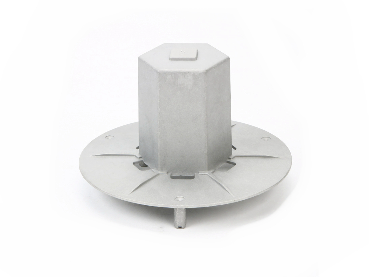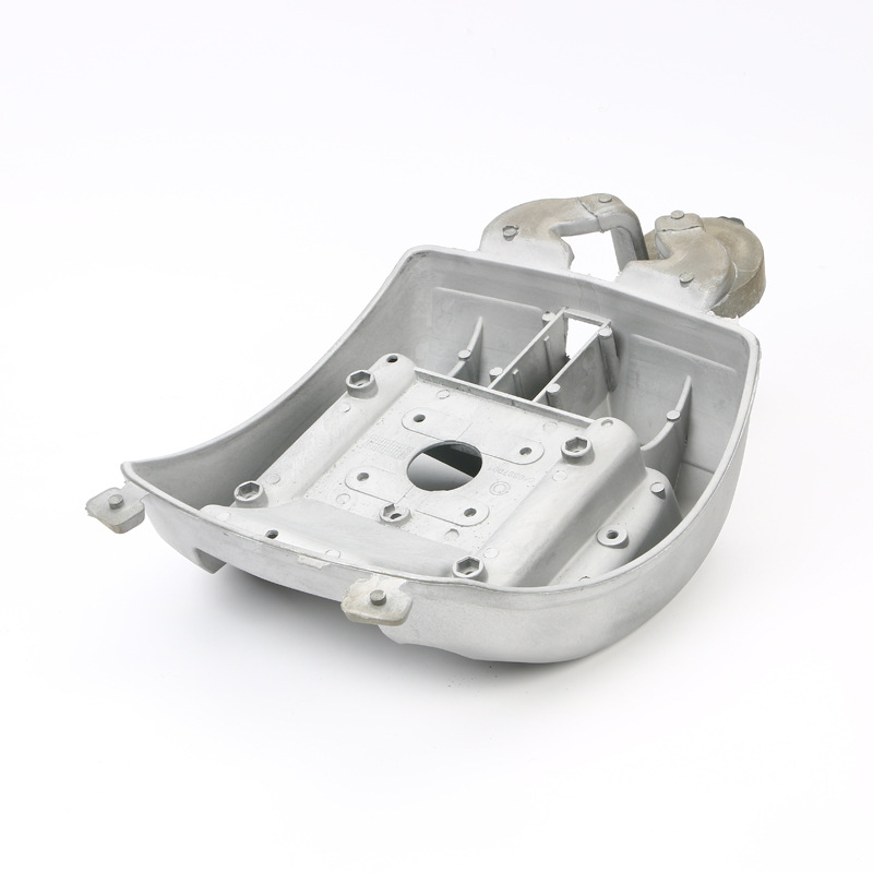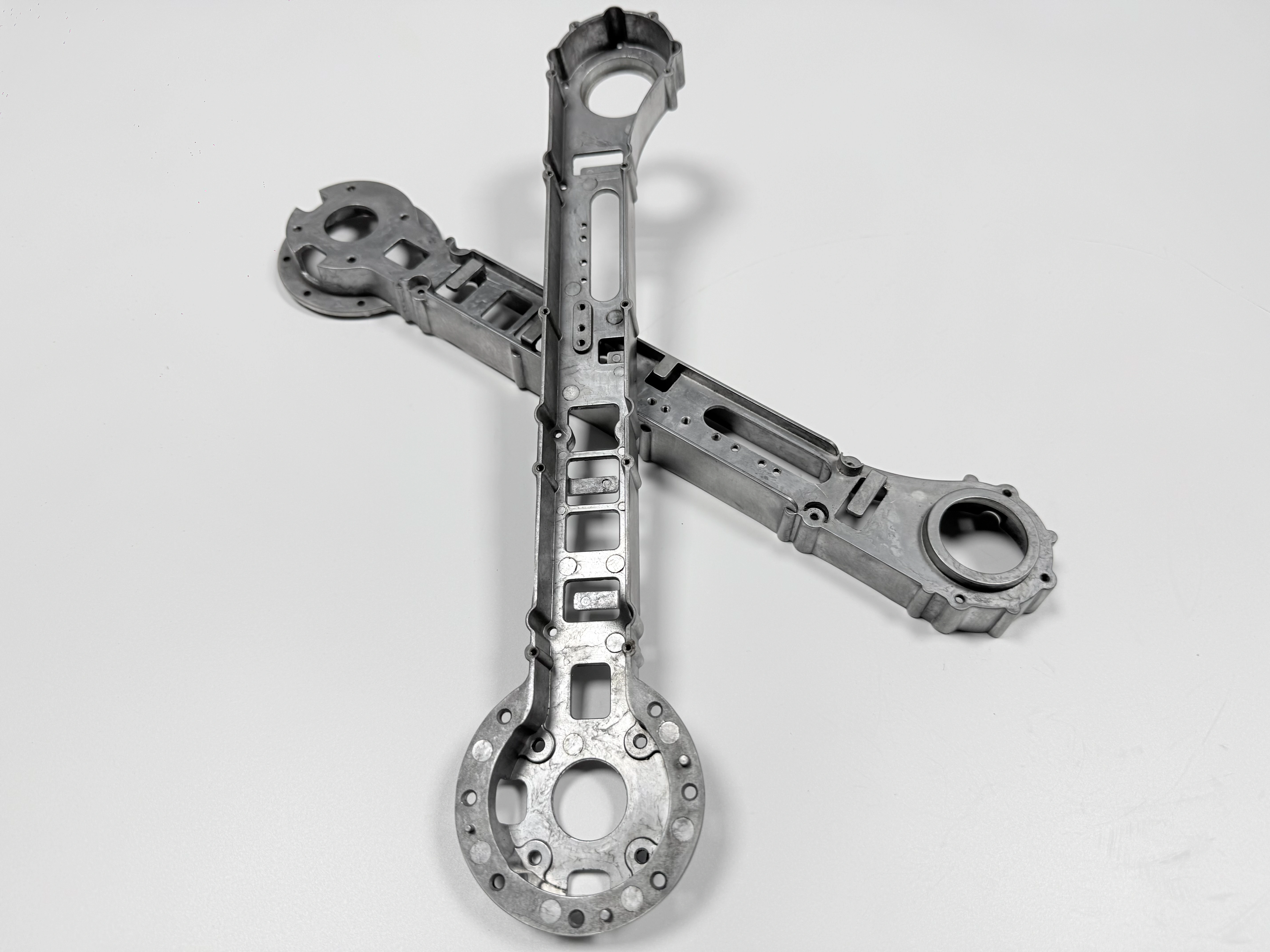
Aluminum Die Casting a Robot Exoskeleton Frame: 1.5 mm, T6
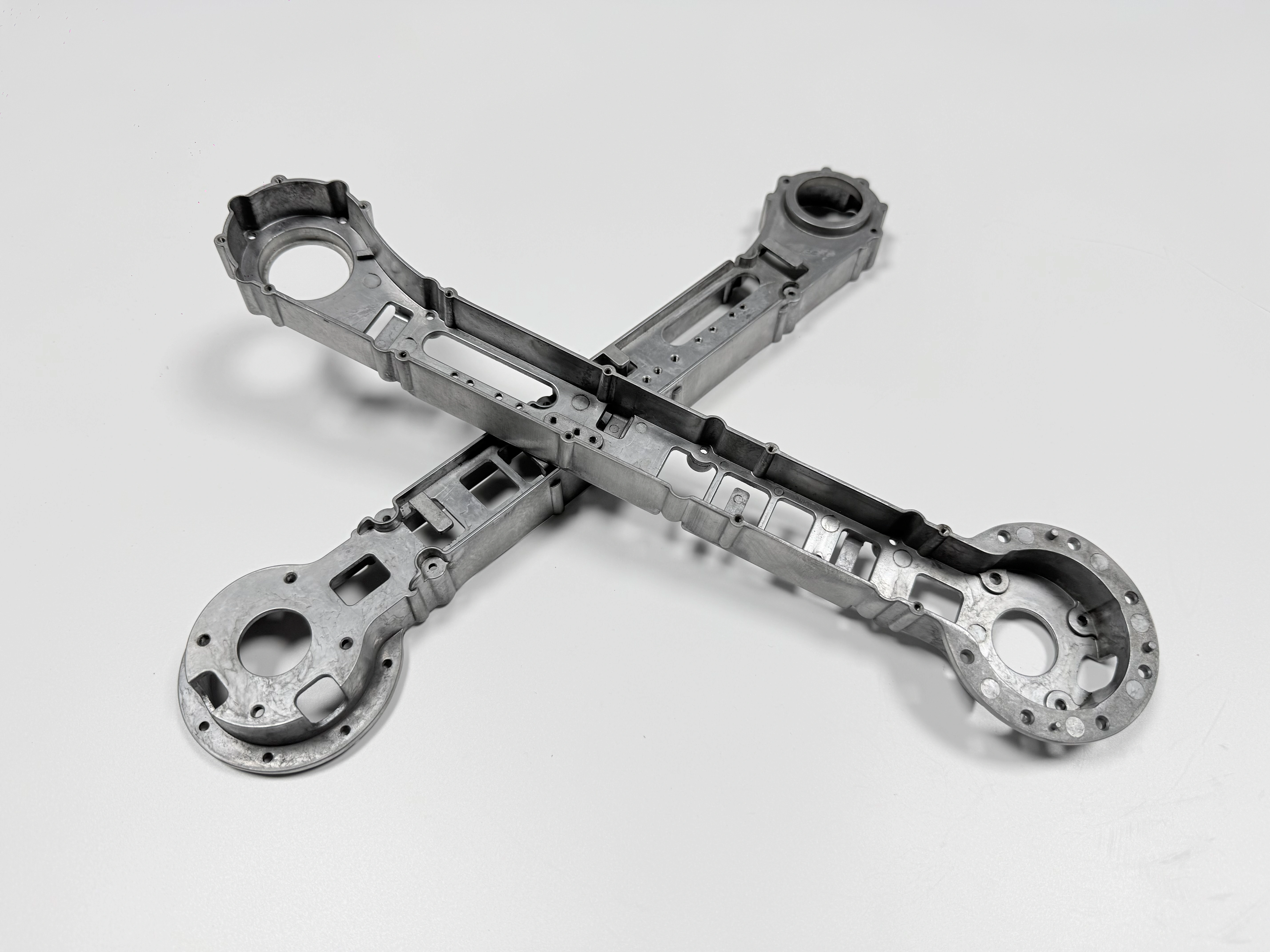
An aluminum die casting robot frame in ADC12 carries three requirements that no single step can hold: a 1.5 mm wall, joint seats within ±0.02 mm, and a 400 MPa target after T6 heat treatment. The wall is decided while the die fills, the seats after the quench, and the tensile target in the furnace. The route that keeps all three runs vacuum die casting, gate removal, T6, straightening, CNC, micro-arc oxidation with masking, then final inspection.
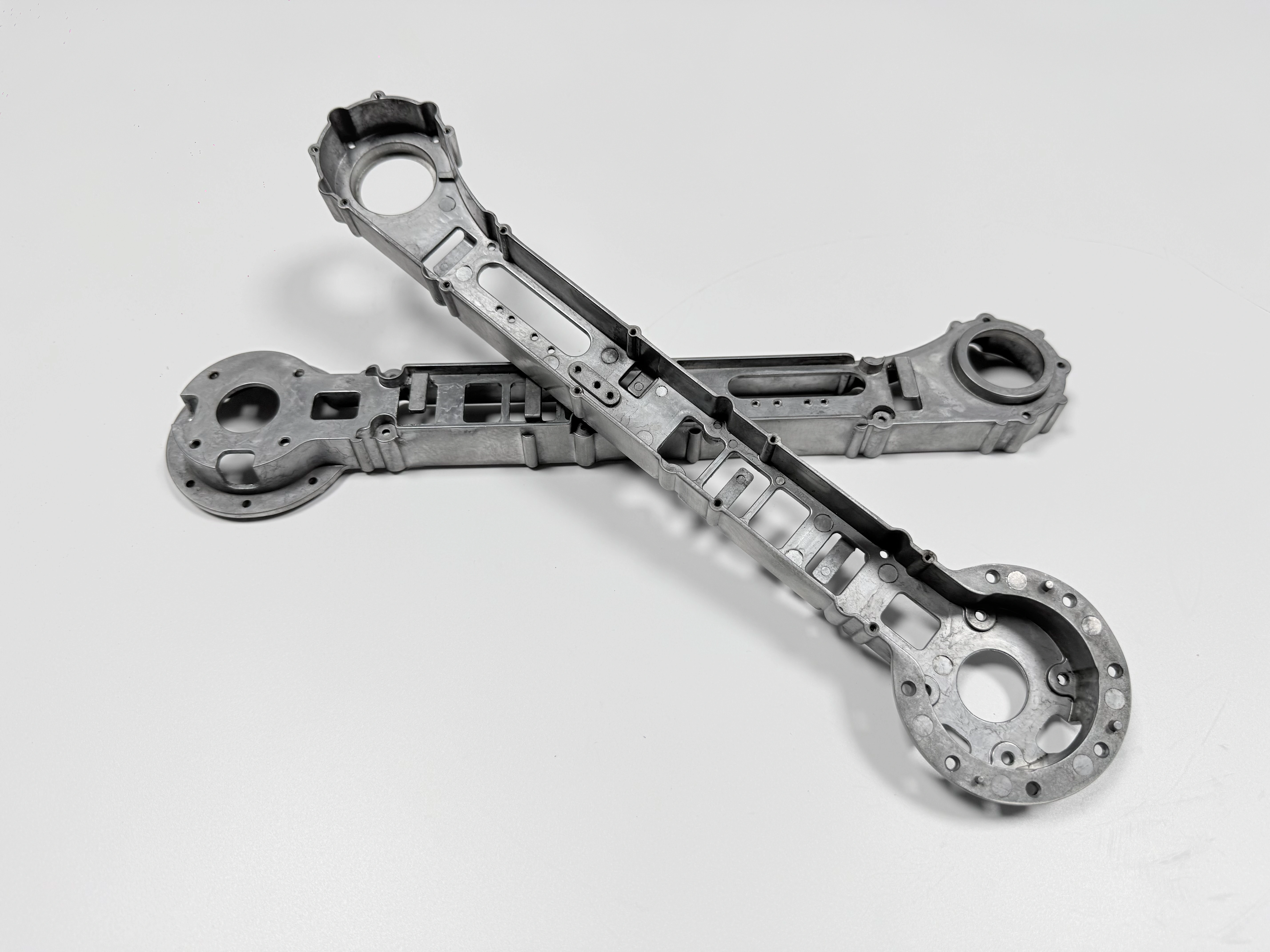
Three Numbers, One Part: 1.5 mm, ±0.02, 400 MPa
Each requirement fails at its own stage, so one inspection cannot clear all three. A wall short of 1.5 mm shows at the fill check, a seat out of ±0.02 mm shows on the CMM after the cut, and a tensile target missed shows on a test bar. A quote that folds the three into one machining tolerance has already lost the first two.
The casting leaves the die as a blank with stock on the joints and no finished face. The alloy is ADC12, whose nearest ASTM B85 grade is A383, and the 1.5 mm wall is a drawing target rather than a shop default. Table 1 pairs each number with the step that sets it and the check that proves it.
Requirement | Target (mm, MPa) | Set at | Proved by |
|---|---|---|---|
Wall | 1.5 mm | Vacuum fill, one cavity, overflow at the far end | X-ray or CT scan |
Joint seat | ±0.02 mm | Straightening, then CNC from the datum | CMM point map |
Seat flatness | 0.03 mm | Final cut on the machined face | CMM, free state |
Hole position | ±0.02 mm | Fixture and program after the cut | CMM point map |
Tensile strength | 400 MPa target | T6 at 490–510 °C, then 150–170 °C aging | Test bar to ASTM B557 |
What the Drawing Must Fix Before Tooling
The drawing fixes four items before the die is cut: the datum face, the stock left on it, the mask list, and the heat-treat state. A frame drawing that names ADC12 and a wall thickness but leaves the datum to the shop produces blanks that do not interchange between batches. The datum is the machined joint seat; the as-cast 1.5 mm wall cannot serve as one.
Stock has to cover quench distortion plus the cut. Name the face, the allowance on it, and every dimension measured from it on one sheet. Datum strategy for cast and machined parts starts from that callout, and the heat-treat line reads T6 pending shop confirmation.
One Cavity, H13, Vacuum: Why the Die Looks Like This
A 1.5 mm wall needs a fill window that a multi-cavity die cannot give at this part size. One cavity keeps the shot weight and the vent area in proportion, and the vacuum system pulls gas from one fill instead of four. The die is cut in H13 hot-work steel with a design target of 200,000 shots.
Overflow sits at the far end of the thin wall, where the metal arrives last and coldest. H13 holds wall detail through the run and takes the thermal cycling a thin core sees. A second cavity would double output and halve the pressure window at the same time, so the die tooling decision follows the wall thickness and the fill window.
Hypothetical Engineering Scenario: a 320 × 180 × 90 mm exoskeleton frame with a 1.5 mm wall and a finished weight target of 1.2–1.8 kg. The figures are drawing targets, not a measured batch. At that envelope, one cavity keeps the fill distance inside a window a single vacuum shot can hold.
Filling 1.5 mm Without Cold Shut: Where the Metal Stops
At 1.5 mm the metal front loses heat to the die on both faces and can freeze before two streams meet. The result is a cold shut, a lap that reads as a line on the surface and as a crack under load. Pressure alone does not close it, because a frozen front cannot be pushed into a wall.
Vacuum lowers the gas the front has to push, and a gate aimed at the thick joint boss keeps the fastest metal moving toward the thin section. The overflow then has to be large enough to accept the cold front. None of this shows on the surface, so an X-ray or CT scan is the check that counts.
A 3 mm wall on the same frame hides the failure for a while; at 1.5 mm the window closes faster than an operator can react. Wall thickness starting point explains where that limit comes from on an enclosure.
T6 at 490–510 °C: The Blister Gate
The T6 window is where the 400 MPa target and the blister risk are decided together. Solution treatment at 490–510 °C takes copper and silicon into solution, the quench locks the structure, and aging at 150–170 °C precipitates the hardening phase. The 400 MPa figure is a target for that finished state; the as-cast alloy is not held to it.
Gas pores expand as the metal softens at solution temperature, and a pore near the skin lifts it. That is why vacuum die casting runs before T6 instead of after: the gas has to leave the casting before the furnace sees it. Feasibility for a given frame is confirmed with the heat-treat shop before the die is cut.
When the gas reading will not support T6, the fallback is T5, and the drawing changes with it. A test bar poured with the part and pulled to ASTM B557 reports what the furnace did to that heat. Aluminum die casting heat treatment covers the same window from the metallurgy side.
Straightening: Between Quench and the Cut
Straightening exists because quenching leaves the frame outside its stock allowance. The 1.5 mm wall cools before the joint boss, and the frame warps toward the thick side. Straightening after T6 and before CNC brings the blank back; skip it and the cutter runs out of material on one corner.
Two orders are possible, and the second table sets them side by side. One holds ±0.02 mm on the seat; the other moves the error into machining hours and the scrap bin.
Order | What it holds (mm) | What it costs | Where it fails |
|---|---|---|---|
Straighten after T6, then cut | Seat within ±0.02 mm with stock left for the cut | One press step and a stress-relief check | A warp that springs back after the press |
Cut first, straighten after | The cut size as machined | A second cut on every seat and a re-check | Straightening moves the seat that was just cut |
The seat is cut after straightening from the datum, and the 0.03 mm flatness target comes off that cut. Distortion left after the press shows as a taper across the seat, which is why a CMM point map decides instead of a single reading.
CNC: ±0.02 mm on the Joint Seat
The joint seat and the holes are cut in one setup from the same datum, so the seat and the hole pattern share one reference. A seat held to ±0.02 mm is a machining result, and it holds only when stock, fixture, and program agree. A second setup adds a second error to the stack.
Clamping a 1.5 mm wall springs it. The fixture supports the boss and pulls down near the cut, so the thin web carries no clamp load, and the part is checked as it will be bolted. CNC machining of castings starts from the blank condition, and fixture design for machined castings covers the support plan.
A seat that measures inside tolerance in the fixture and outside it on the plate is a clamping problem, not a cutter problem. That reading sends the fix back to the fixture instead of the program.
Flatness 0.03 and Hole Position ±0.02: What the CMM Reads
Flatness of 0.03 mm is read on the machined face in free state, before the frame is bolted to anything. A plate reading taken with the part clamped measures the fixture, not the part. The drawing has to name which state applies, or two inspectors will report two results from one frame.
Hole position at ±0.02 mm is checked on a CMM point map covering the pattern, not on a single hole. Slotted holes in the mating frame can relax that callout, and the decision is made before the fixture is built. Post-machining of castings carries the cut and the re-check in one release.
MAO: A Film That Grows Both Ways
Micro-arc oxidation grows a ceramic film out of the aluminum itself, with no plating underlayer to peel. The film consumes metal inward and builds outward, so a coated face sits above the cut surface and a coated bore closes. Fit is the first thing the process changes.
Film thickness on this alloy is not fixed yet, so the drawing leaves the number open and the mask list protects the fit. Seats, threads, grounding points, and datums stay bare. A part coated before the final cut loses the seat tolerance it was machined to.
Coating runs after CNC for that reason, and a film thickness gauge checks what the bath produced. MAO coating on aluminum covers the layer system, and arc anodizing explains how the layer forms.
Masking Is a Drawing Decision: Fix It Before the PO
Four surfaces stay bare: threads, fits, grounding points, and datums. A missed item does not show at the coating tank, because the film looks uniform over a masked area and over a thread alike. It shows at assembly, when a screw bottoms or a seat will not close.
The remedy is a ream or a re-cut, which costs a second pass on every part in the batch. The mask list belongs on the drawing and on the purchase order, and the go/no-go gauge runs after coating, before parts reach the assembly line. Surface finishing covers the options around the coating step.
Inspection: Six Methods Before Release
Six checks release a batch, and each answers a failure the others cannot see. A test bar is pulled to ASTM B557, an X-ray or CT scan covers the thin wall, a CMM point map covers the seats, and go/no-go gauges cover the threads. The coating gets a film thickness reading, and the finish gets a salt spray test whose standard and duration sit on the drawing.
A batch record that carries all six can be compared with the next one; a record with only CMM numbers cannot. The aluminum die casting frame case shows the same record set on a smaller frame. Porosity risk mapping covers how a gas reading is accepted or rejected.
The failure that ties all six together is the one that hides: the casting fills, the surface looks sound, and the blister appears only after T6. Put the six checks and their gauges on the drawing before the RFQ goes out.
FAQ